
Automatic laying molding method for composite connection skirt

A composite material and molding method technology, which is applied to other household appliances, household appliances, household components, etc., can solve the problems of difficulty in ensuring the quality of end-face wire laying, difficulty in connecting skirt transitions for the laying head, and difficulty in connecting skirts. The effect of production cycle, smooth product surface and accurate skirt size

Active Publication Date: 2017-03-22
湖北三江航天江北机械工程有限公司
View PDF6 Cites 8 Cited by
  • Summary
  • Abstract
  • Description
  • Claims
  • Application Information

AI Technical Summary

Problems solved by technology

[0005] However, it is currently difficult to apply this automatic wire laying technology to the forming of the connecting skirt, for the following reasons: 1) It is difficult for the laying head to complete the transition from the connecting skirt ring to the end face; 2) It is difficult to guarantee the quality of the end face laying wire

Method used


Image

  • Automatic laying molding method for composite connection skirt
  • Automatic laying molding method for composite connection skirt
  • Automatic laying molding method for composite connection skirt

Examples


Embodiment 1

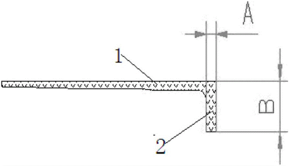
[0035] Such as figure 1 As shown, the composite material connecting skirt includes annulus 1 and end surface 2, A is the thickness of the end surface, and B is the height of the end surface. The specific size requirements are shown in Table 1 below:

[0036] Table 1

[0037] End face diameter / end face height Φ1200±0.5mm End Wall Thickness / End Thickness 6.0±0.3mm Skirt height 250±0.5mm quality 15kg Axial load ≥60 tons

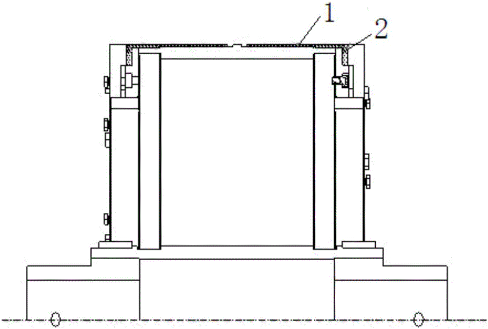
[0038] 1) Forming mold preparation: such as figure 2 As shown, the molds corresponding to the ring surface 1 and the end surface 2 are combined and installed, the surface of the mold is cleaned, and a thin layer of polytetrafluoroethylene tape is wound on the surface (the molding mold is an existing conventional mold).

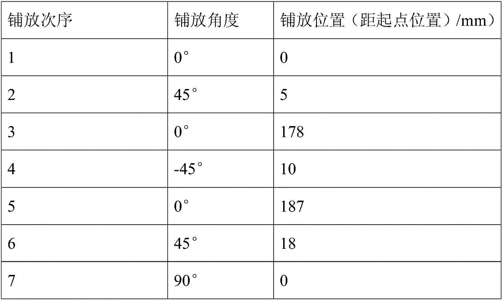
[0039] 2) According to the aforementioned load, quality and size requirements, design 20 layers of layup, the layup angle, order and position are shown in Table 2 below, and use the hot-melt method ...

Embodiment 2

[0053] The structure and size requirements of the composite connecting skirt are shown in Table 3 below:

[0054] table 3

[0055] End diameter Φ1100±0.5mm End wall thickness 7.2±0.3mm Skirt height 300±0.5mm quality ≤20kg Axial load ≥50 tons

[0056] 1) Forming mold preparation: install the mold assembly, clean the surface of the mold, and wind a thin layer of polytetrafluoroethylene tape on the surface.

[0057] 2) According to the aforementioned load, quality and size requirements, design 24 layers of layup, the layup angle, order and position are shown in Table 4 below, and use the hot-melt method to make carbon fiber prepreg, and the prepreg is T700 carbon fiber + epoxy resin system:

[0058] Table 4

[0059]

[0060]

[0061] 3) Carry out automatic wire laying according to the laying angle, position and sequence in Table 1, and all laying layers of the composite material connecting skirt are divided into 0°, ±45°, 90°, ...


PUM

PropertyMeasurementUnit
diameteraaaaaaaaaa
diameteraaaaaaaaaa
thicknessaaaaaaaaaa

Abstract

The invention discloses an automatic laying molding method for a composite connection skirt. The automatic laying molding method comprises the steps of 1, manufacturing a molding mold; 2, cutting preimpregnation filaments; 3, laying the preimpregnation filaments on the surface of the molding mold automatically with a laying-winding integrated machine, wherein in the automatic filament laying process, after the filaments are completely laid on an annular face through a laying head, the filaments are laid to corners between end faces and the annular face, a compression roller is made to break away from the surface of the molding mold, filament laying is conducted in a suspended manner for the height equivalent to 1-2.5 times the end face height through the laying head, filament bundles are cut off, then the molding mold rotates for the angle equivalent to one time the yarn tape width, the laying head returns to the starting laying point, after single-layer filament laying action is completed, the preimpregnation filaments on the end faces are compacted, and the filaments are laid circularly layer by layer till laying is completed; 4, conducting curing; and 5, conducting demolding. By means of the automatic laying molding method for the composite connection skirt, automated production is technologically achieved; the production cycle is greatly shortened, and production efficiency is greatly improved; and a connection skirt product obtained through the automatic laying molding method is smooth in surface, and a skirt body is precise in dimension and high and stable in quality.

Description

technical field [0001] The invention relates to a molding method of a solid rocket motor shell, in particular to an automatic laying molding method of a composite material connecting skirt. Background technique [0002] The connecting skirt of the solid rocket motor casing is an integral extension of the casing, which is used to realize the connection between the missile stages or other parts. The connecting skirt needs to withstand various loads such as axial pressure, bending moment, shear and internal pressure. The power situation is more complicated. With the development of material science, the solid rocket motor connecting skirt is gradually replaced by the composite material connecting skirt from the metal connecting skirt, and has developed from the early single glass fiber composite skirt to the high performance hybrid and full carbon composite skirt. [0003] At present, domestic solid rocket motor composite connecting skirts are usually formed by manual laying + ...

Claims


Application Information

Patent Timeline
Patent Type & Authority Applications(China)
IPC IPC(8): B29C70/38B29C70/34B29L31/30
CPCB29C70/342B29C70/382B29L2031/3097B29L2031/749
Inventor 李天明高李帅黄泽勇曾甜甜邓德凤
Owner 湖北三江航天江北机械工程有限公司
Learn More