Energy-saving and lighting handrail used for bus

An energy-saving lighting and bus technology, applied in the field of buses, can solve problems such as energy waste, energy loss, and no better technical solutions, and achieve the effect of saving energy and reducing energy loss

Inactive Publication Date: 2017-03-22
林飞飞
View PDF8 Cites 7 Cited by
  • Summary
  • Abstract
  • Description
  • Claims
  • Application Information

AI Technical Summary

Problems solved by technology

[0002] As a common tool in urban transportation, buses have been widely used. In the existing urban public transportation system, buses often need to start and stop repeatedly during the movement process. It also needs to be in repeated movement and stop loading, and when the number of passengers on the bus is too large, some passengers cannot sit on the bus and need to stand on the bus. At this time, for passengers standing on the bus, The handrails set on the bus are particularly important. Passengers usually use the handrails to balance their own movements, and transfer most of the kinetic energy of the body to the car body through the handrails. This part of energy itself comes from the car body itself. If the Kinetic energy directly acts on the car body, and the energy will eventually be dissipated in the form of friction, which greatly wastes energy. At the same time, when the bus is running at night, the lighting system inside the car is mostly powered by an extra generator on the car body. , the additional preparation of lighting generators will also bring corresponding energy losses, and in the bus system, how to use the kinetic energy generated by the repeated movement of the passengers in the bus during the operation of the bus has not been better in the prior art. technical solutions

Method used


Image

  • Energy-saving and lighting handrail used for bus
  • Energy-saving and lighting handrail used for bus
  • Energy-saving and lighting handrail used for bus

Examples


Embodiment Construction

[0023] In order to make the technical means, creative features, goals and effects achieved by the present invention easy to understand, the present invention will be further described below in conjunction with specific embodiments.

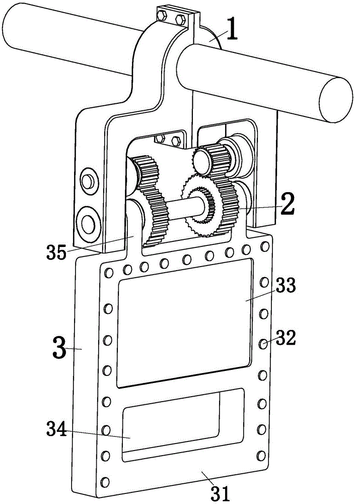
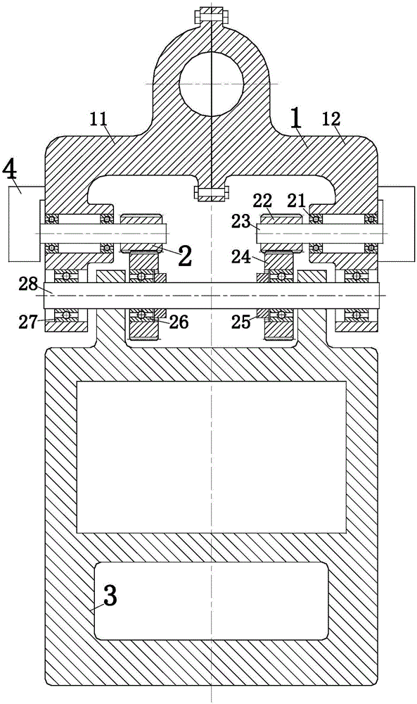
[0024] Such as Figure 1 to Figure 3 As shown, an energy-saving lighting handrail for a bus according to the present invention includes an installation body 1, a transmission device 2, a handle 3, a power generation module 4 and a power storage module, and the installation body 1 and the handrail bracket on the bus As a preferred solution of the present invention, the installation body 1 includes a left installation body 11 and a right installation body 12, and the left installation body 11 and the right installation body 12 are connected by bolts, which is convenient for the later use of the present invention Installation during the process; the transmission device 2 is installed on the installation body 1, and the transmission device 2 is used t...


PUM


Abstract

The invention relates to a bus, in particular to an energy-saving and lighting handrail used for a bus. The energy-saving and lighting handrail used for the bus comprises a mounting body, a transmission device, a handle, an electricity generating module and an electricity storing module. the mounting body is connected with a handrail frame in the bus, the transmission device is arranged on the mounting body, and the handle is connected with the transmission device; the electricity generating module is connected with the mounting body, the electricity storing module is arranged on the mounting body, and the electricity storing module is connected with the electricity generating module. The energy-saving and lighting handrail used for the bus adopts a ratchet wheel pawl transmission used for filling and mining to transmit, the one-way rotating demand of an existing electricity generating module is met, and through the design of the direction of turning of a pawl, the electricity generating function can be achieved in the bidirectional process of the front and back movements of the handle; and kinetic energy generated in the bus running process of passengers in the bus is changed into lighting electric energy, energy loss can be greatly reduced, and energy can be saved.

Description

technical field [0001] The invention relates to a bus, in particular to an energy-saving lighting handrail for a bus. Background technique [0002] As a common tool in urban transportation, buses have been widely used. In the existing urban public transportation system, buses often need to start and stop repeatedly during the movement process. It also needs to be in repeated movement and stop loading, and when the number of passengers on the bus is too large, some passengers cannot sit on the bus and need to stand on the bus. At this time, for passengers standing on the bus, The handrails set on the bus are particularly important. Passengers usually use the handrails to balance their own movements, and transfer most of the kinetic energy of the body to the car body through the handrails. This part of energy itself comes from the car body itself. If the Kinetic energy directly acts on the car body, and the energy will eventually be dissipated in the form of friction, which g...

Claims


Application Information

Patent Timeline
IPC IPC(8): B60N3/02B60Q3/267
CPCB60N3/026
Inventor 林飞飞
Owner 林飞飞
Why Eureka
Try Eureka