Deformable lift and buoyancy integrated aircraft aerodynamic configuration

An aerodynamic shape, aircraft technology, applied in aircraft parts, fuselage, weight reduction and other directions, can solve problems such as poor maneuverability, large additional weight, wing deformation, etc., achieve wind resistance performance and maneuverability, reduce aircraft weight, The effect of high structural strength

Active Publication Date: 2017-03-22
BEIHANG UNIV
View PDF5 Cites 8 Cited by
  • Summary
  • Abstract
  • Description
  • Claims
  • Application Information

AI Technical Summary

Problems solved by technology

However, these types of aircraft also have their obvious disadvantages: the high-altitude airship is too large, the flight speed is low, the maneuverability is poor, the wind resistance is poor, and the transportation, storage and maintenance costs are very high
Due to the limitation of solar power, the weight of the solar aircraft must be very light, which greatly limits its ability to carry loads, and the body structure has to sacrifice strength and rigidity due to the pursuit of light weight. In order to pursue high aerodynamic efficiency, the wings often use large The chor

Method used


Image

  • Deformable lift and buoyancy integrated aircraft aerodynamic configuration
  • Deformable lift and buoyancy integrated aircraft aerodynamic configuration
  • Deformable lift and buoyancy integrated aircraft aerodynamic configuration

Examples


Embodiment

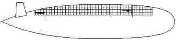
[0028] The design maximum hovering height h=15km and the maximum volume V=140000m 3 , the ratio of the maximum volume to the minimum volume of the fuselage K=6.3.

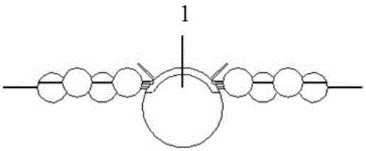
[0029] The chord length of each truss is obtained by calculating the geometric relationship between the deformed trusses: assuming that the distance between the two revolving pairs 12 on the wing spar 10 is a, the chord length of the first truss H1 and the fifth truss H5 is 1.11a, the The chord length of the third truss H3 and the fourth truss H4 is 0.94a, and the chord length of the third truss H3 is 0.85a. Assume that the angle between the first truss H1 and the vertical direction is θ. When the aircraft is parked on the ground, θ=28.4°. During the deformation and ascent of the aircraft, when the flight altitude is 11km, θ reaches the maximum value of 51.6°. At this time, the truss H2, Both H3 and H4 are in the horizontal position. When the flying height reaches the maximum hovering height of 15km, θ=30.4°, and ...


PUM


Abstract

Belonging to the technical field of aircraft design, the invention discloses a deformable lift and buoyancy integrated aircraft aerodynamic configuration. The aerodynamic configuration has a single-fuselage, tandem wing and horizontal tail-free layout, double vertical tails tilt outward certain angle, wings are located at the upper part of the fuselage, front wings and back wings have the same design. The fuselage can produce radial deformation, the fuselage is divided into a front section, a middle section and a back section, and the three sections of the fuselage deform respectively. Because of the introduction of dynamic lift, the aircraft has higher flight height than an airship, greater flight speed, and stronger wind resistant performance and maneuverability; and due to the introduction of static lift, the aircraft has loading capacity far higher than that of conventional high-altitude unmanned aerial vehicles, and has higher structural height and strength. In the process of vertical rising and fall, the fuselage can produce corresponding deformation to change the fuselage volume so as to guarantee the fuselage lift and the aircraft weight balance. With no need for ballonet and ancillary equipment in conventional airships and lift and buoyancy integrated aircrafts, the deformable lift and buoyancy integrated aircraft aerodynamic configuration provided by the invention can reduce the aircraft weight and decrease the ground parking volume of the aircraft.

Description

technical field [0001] The invention belongs to the technical field of aircraft design, and relates to a deformable aerodynamic shape of a lift-floating integrated aircraft, in particular to an aerodynamic shape of an aircraft which comprehensively utilizes dynamic lift and static lift and whose fuselage can be adaptively deformed. Background technique [0002] Near-space flight platforms have broad application prospects. For this kind of high-altitude and long-endurance aircraft platform, high-altitude airships, solar-powered aircraft, and lift-and-float integrated aircraft are currently the most researched directions. But these kinds of aircraft also have their obvious disadvantages: high-altitude airships are too bulky, low flying speed, poor maneuverability, poor wind resistance, and high transportation, storage and maintenance costs. Due to the limitation of solar power, the weight of solar aircraft must be very light, which greatly limits its ability to carry loads, an...

Claims


Application Information

Patent Timeline
IPC IPC(8): B64C1/06B64C1/12B64C3/18
CPCB64C1/061B64C1/064B64C1/065B64C1/12B64C3/18Y02T50/40
Inventor 马东立李冠雄杨穆清王少奇郭阳
Owner BEIHANG UNIV
Why Eureka
Try Eureka