
An automatic vacuum packaging machine

A technology of vacuum packaging machine and packaging machine, which is used in packaging, packaging, transportation packaging and other directions under vacuum/special atmosphere, can solve the problems of low work efficiency, slow system running speed, grasping shaking, etc. The effect of fast speed and high production efficiency

Active Publication Date: 2018-10-09
尚威自动化工程(昆山)有限公司
View PDF5 Cites 0 Cited by
  • Summary
  • Abstract
  • Description
  • Claims
  • Application Information

AI Technical Summary

Problems solved by technology

[0002] At present, there are horizontal vacuum packaging machines, rotary vacuum packaging machines and horizontal vacuum packaging machines commonly available in the market. Due to the limitations of occasions and materials, horizontal packaging machines and rotary vacuum packaging machines are used more , with the rise of labor costs, site constraints and increases in production capacity, the existing vacuum packaging machines can no longer meet the market's requirements for high output, high stability and low energy consumption
[0003] The grasping device in the existing vacuum packaging machine cannot firmly grasp and put multiple products into the vacuum chamber at one time, and often shakes when grasping, and the vacuum chamber can only be used for a single bag or several bags at a time. Bag products are vacuum-sealed, and the upright transportation of the packaging bags cannot be guaranteed. When the packaging is sealed, it is prone to deformation, twisting, etc., which affects the sealing quality, and the entire system runs slowly and has low work efficiency.

Method used


Image

  • An automatic vacuum packaging machine
  • An automatic vacuum packaging machine
  • An automatic vacuum packaging machine

Examples


Embodiment Construction

[0032] The following takes the eight-chamber automatic vacuum packaging machine as an example and introduces it in detail with the accompanying drawings.

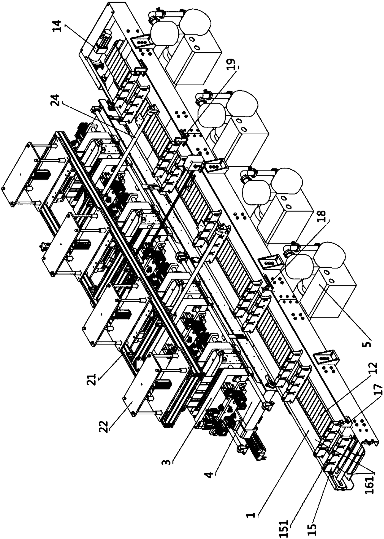
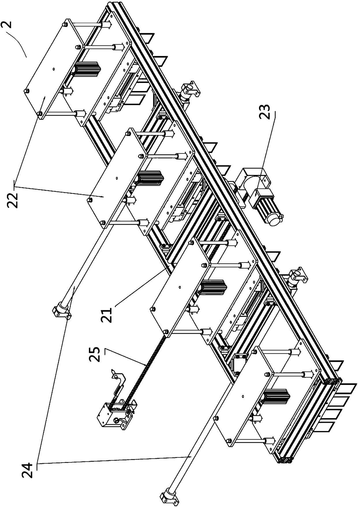
[0033] like figure 1 As shown, the eight-chamber automatic vacuum packaging machine includes a conveying chain plate device 1, an output device 4 located on one side of the conveying chain plate device, a vacuum sealing device 3 located above the output device, and a bag grabbing device 2 located above the vacuum sealing device .

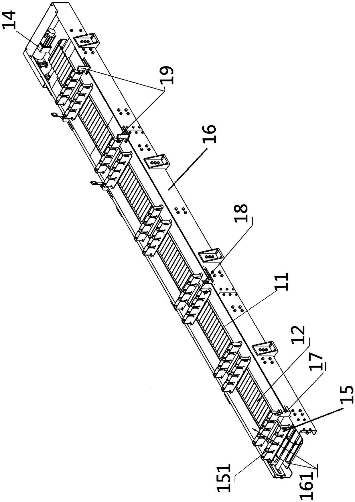
[0034] like figure 2 As shown, the conveying chain plate device 1 includes a bracket 16, sprockets installed at both ends of the roller on the bracket 16, a chain 11 connected to the sprocket and running in the horizontal direction, a chain plate 12 fixed on the chain by buckles, The servo motor A14 connected to the shaft where the chain is located and the bag slot 15 fixed on the chain plate, the bag slot is vertically fixed on the conveyor chain plate by bolts, there are 4 sets of bag slots,...


PUM


Abstract

The invention discloses an automatic vacuum packaging machine. The automatic vacuum packaging machine comprises a conveying chain plate device, a bag grabbing and transferring device, a vacuum sealing device and an output device. The conveying chain plate device is provided with bag containing grooves. The bag grabbing and transferring device comprises supporting shafts A, a frame arranged on the supporting shafts A, and grabbing devices arranged on the frame. Each grabbing device is provided with a clamping plate. The vacuum sealing device comprises movable cavities and fixed cavities opposite to the movable cavities. Each movable cavity is provided with a sealing block A, a separation rod and a centralizing push plate. A bag pressing block is arranged between every two adjacent separation rods. Each fixed cavity is provided with a sealing block B, a bag pressing strip and a backup plate. Each fixed cavity is provided with a vacuum pressure detection meter, a vacuum breaking pagoda connector and a vacuum pagoda connector connected with a vacuum pump. The automatic vacuum packaging machine is high in unit yield, complete automatic control is achieved, and independent vertical conveying and the sealing quality of each packaging bag can be guaranteed; and bagging and vacuum sealing requirements of various materials can be met, and the automatic vacuum packaging machine is high in yield, high in stability and low in energy consumption.

Description

technical field [0001] The invention belongs to the field of packaging equipment, in particular to an automatic vacuum packaging machine. Background technique [0002] At present, there are horizontal vacuum packaging machines, rotary vacuum packaging machines and horizontal vacuum packaging machines commonly available in the market. Due to the limitations of occasions and materials, horizontal packaging machines and rotary vacuum packaging machines are used more , with the rise of labor costs, site constraints and increases in production capacity, the existing vacuum packaging machines can no longer meet the market's requirements for high output, high stability and low energy consumption. [0003] The grasping device in the existing vacuum packaging machine cannot firmly grasp and put multiple products into the vacuum chamber at one time, and often shakes when grasping, and the vacuum chamber can only be used for a single bag or several bags at a time. Bag products are vac...

Claims


Application Information

Patent Timeline
Patent Type & Authority Patents(China)
IPC IPC(8): B65B31/02B65B43/46B65B51/10B65B35/24B65G39/16
CPCB65B31/024B65B35/24B65B43/465B65B51/10B65G39/16
Inventor 吕阳
Owner 尚威自动化工程(昆山)有限公司
Learn More