
Straw distributing equipment

A straw and equipment technology, which is applied in the field of material distribution devices, can solve the problems of easy bridging and poor supply continuity, and achieve the effects of eliminating bridging, ensuring stability and improving continuity.

Inactive Publication Date: 2017-03-22
WUXI XIDONG ENERGY TECH
View PDF14 Cites 2 Cited by
  • Summary
  • Abstract
  • Description
  • Claims
  • Application Information

AI Technical Summary

Problems solved by technology

[0003] In view of the above problems, the present invention provides straw material distribution equipment, which can solve the technical problems of the prior art in the prior art, such as poor supply continuity and prone to bridging.

Method used


Image

  • Straw distributing equipment
  • Straw distributing equipment
  • Straw distributing equipment

Examples


Embodiment Construction

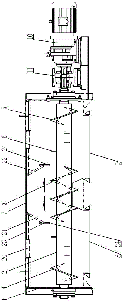
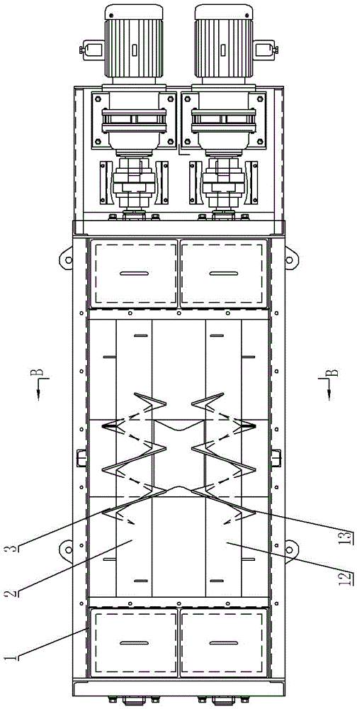
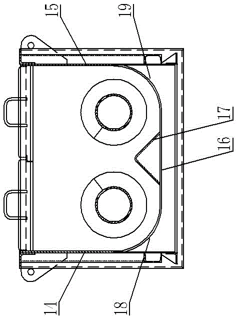
[0014] Such as Figure 1~Figure 3 As shown, it includes a housing 1, a material inlet 7 is opened on the top of the housing, and a material outlet 8, 9 is opened at the bottom of the housing. The rotating shafts 2, 12 are supported on the left and right side walls of the housing side by side. They are separately driven by a driving device, the driving device includes a geared motor 10, the output shaft of the geared motor 10 is fixedly connected to the corresponding rotating shaft through a coupling 11, and the geared motor is fixed on the supporting plate on the side of the housing through the motor seat;

[0015] Rotating shafts 2 and 12 are located below the feed inlet and are correspondingly fixed with middle helical blades 3 and 13, and are correspondingly fixed with stirring rods 6 at the part above the discharge opening, and the middle helical blades of the two rotating shafts are set in reverse;

[0016] Material guide plates 21, 22 are arranged symmetrically below the...


PUM


Abstract

The invention provides straw distributing equipment which can solve the technical problems that in the prior art, during straw stokehold distributing and supplying, the supply continuity is poor, and the bridging phenomenon is prone to occurrence. The straw distributing equipment comprises a shell, rotating shafts and a driving device for driving the rotating shafts to rotate, a feeding opening is formed in the top of the shell, and two discharging openings are formed in the bottom of the shell; the straw distributing equipment is characterized in that the two rotating shafts are supported to the left side wall and the right side wall of the shell in parallel, the parts, located below the feeding opening, of the rotating shafts are provided with middle spiral blades, the parts, located above the discharging openings, of the rotating shafts are provided with stirring rods, and the middle spiral blades of the two rotating shafts are arranged in the reversed directions; material guide plates are symmetrically arranged below the feeding opening, the portions on the upper sides of the material guide plates are hinged to a piston rod of an air cylinder, and the rotating shafts are arranged at the positions on the lower sides of the material guide plates; the air cylinder and the shell are fixedly connected, the two ends of each rotating shaft are inserted into guide grooves in the front side inner wall and the back side inner wall of the shell, and springs are arranged at the portions, located in slot bodies of the two sides of the rotating shafts, of the guide grooves.

Description

technical field [0001] The invention relates to a material distributing device, in particular to straw material distributing equipment. Background technique [0002] Straw is an important part of biomass, and it is the fourth largest energy source in the world after coal, oil and natural gas. It is widely used in the field of heating and power generation. However, the three-way feeder is often used for material distribution in front of the furnace, and the three-way feeder controls the steering of the straw by turning over the flap to achieve the purpose of material distribution. However, the two material distribution ports are intermittent feeding, and the straw supply The continuity is poor, and bridging phenomenon is prone to occur, which restricts the stable operation of the boiler. Contents of the invention [0003] In view of the above problems, the present invention provides straw material distribution equipment, which can solve the technical problems of poor suppl...

Claims


Application Information

Patent Timeline
Patent Type & Authority Applications(China)
IPC IPC(8): B65G33/18B65G33/24B65G33/34
CPCB65G33/18B65G33/24B65G33/34
Inventor 袁绍生诸家敏
Owner WUXI XIDONG ENERGY TECH
Learn More