A Pneumatic Splitting Structure for Plates

A technology of sheet metal and cylinder, applied in the field of sheet metal pneumatic splitting structure, can solve problems such as split sheet is not easy to separate

Inactive Publication Date: 2018-08-28
保定苏博汽车零件制造有限公司
View PDF9 Cites 0 Cited by
  • Summary
  • Abstract
  • Description
  • Claims
  • Application Information

AI Technical Summary

Problems solved by technology

[0003] The purpose of the present invention is to provide a pneumatic sheet material splitting structure, which solves the problem that existing magnetic thick sheet materials, large sheet materials and non-magnetic materials are difficult to separate.

Method used


Image

  • A Pneumatic Splitting Structure for Plates
  • A Pneumatic Splitting Structure for Plates

Examples


Embodiment Construction

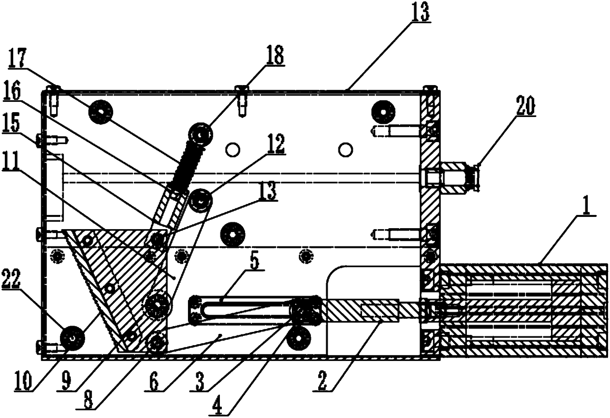
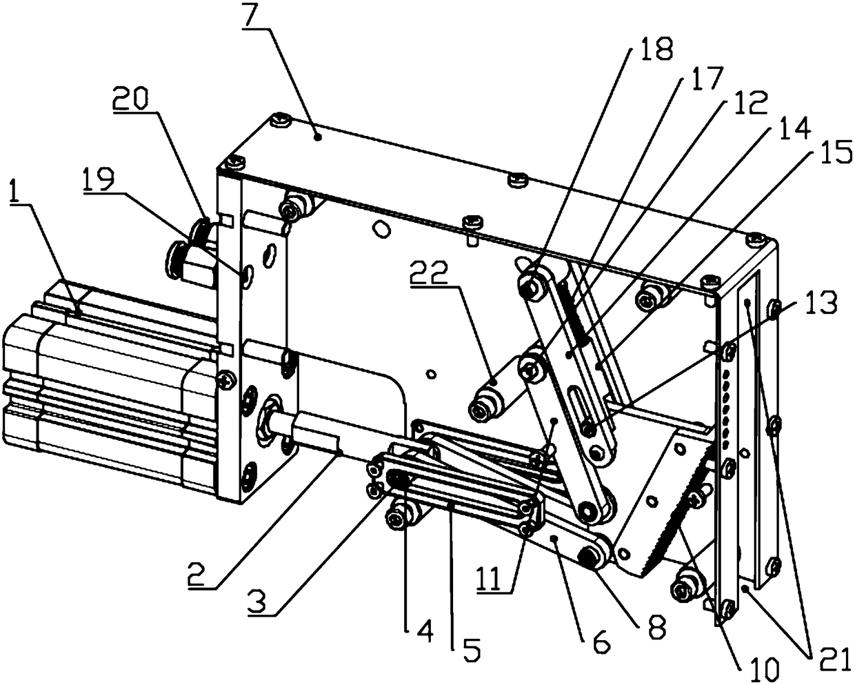
[0016] Such as figure 1 and 2 As shown, a sheet material pneumatic splitting structure includes a hollow shell 7, the outer end of the shell 7 is fixed with a cylinder 1, and the driving end of the cylinder 1 extends to the inside of the shell 7 and is connected to the cylinder One end of the rod 2 is connected, and the other end of the connecting rod 2 of the cylinder is provided with a horizontal through hole, and the first pin shaft 3 is arranged in the through hole, and the two ends of the first pin shaft 3 are respectively hinged to a first connecting rod 6, and the other ends of the two first connecting rods 6 respectively extend to both sides of the tail end of a toothed mounting plate 9 and are hinged and fixed by the second pin shaft 8, wherein the two ends of the first pin shaft 3 The two sliding plates 5 are respectively fixedly mounted on the inner wall of the corresponding side plate in the housing 7, and the tail end of the toothed mounting plate 9 is located at...


PUM


Abstract

The invention discloses a plate pneumatic separation structure. The plate pneumatic separation structure comprises a cylinder, a cylinder connecting rod, multiple pin shafts, a slide plate, multiple connecting rods, a cylinder mounting plate, a side plate, a tooth-shaped mounting plate, a tooth-shaped plate, a spring shaft, a spring shaft sleeve and a spring; the cylinder is connected with the cylinder connecting rod; a first connecting rod is hinged with the cylinder connecting rod and the tooth-shaped mounting plate; a second connecting rod and the spring shaft sleeve form a parallelogram connecting rod mechanism; and the cylinder is ejected to drive the tooth-shaped plate to swing along one end of the second connecting rod. In the separation structure, as a certain included angle is formed between the tooth-shaped plate and plates, the tooth-shaped plate only can be contacted with the first plate, and grabs the first plate through a upward turning tooth shape; two ends of the plates synchronously use the mechanism, and synchronously act; when the cylinder is continuously ejected, the tooth-shaped plate can clamp two edges of the plates to upwards move; and as the spring shaft sleeve can be compressed, when the first plate is hoisted, the tooth-shaped plate can be compressed for retraction, the plates are hoisted and deviated from the mechanism to finish the separation action.

Description

technical field [0001] The invention relates to the field of sheet material splitting such as thick plates and magnetic or non-magnetic sheet materials with mutual adsorption, in particular to a pneumatic sheet material splitting structure. Background technique [0002] In the automatic cutting and stamping process of the automobile industry, due to the leveling and storage of steel coils, oiling is required for processing, resulting in oil film adsorption between steel plates, which is not easy to separate. The current method of sheet material separation: 1. Magnetic separation (suitable for thin plates or small-area magnetic materials) 2. The suction cup spreader has a turning mechanism, which can hold the sheet material and turn it over at a certain angle, and then separate the sheet Zhang plate, but it is also suitable for thin plates. 3. Air knife method, this method consumes a lot of energy and is unstable. 4. Mechanical sheeting (not limited to magnetic materials and...

Claims


Application Information

Patent Timeline
Patent Type & Authority Patents(China)
IPC IPC(8): B65G47/88
CPCB65G47/88
Inventor 柴辰龙
Owner 保定苏博汽车零件制造有限公司
Why Eureka
Try Eureka