Dehydrator

A dehydrator, motor-driven technology, applied in the direction of removing liquid/gas/vapor by centrifugal force, can solve the problems of waste of manpower, uneven dehydration of inner and outer layers, and inability to achieve continuous production.

Active Publication Date: 2017-03-22
SHAOXING JINYU TEXITLE NEW TECH CO LTD
View PDF5 Cites 6 Cited by
  • Summary
  • Abstract
  • Description
  • Claims
  • Application Information

AI Technical Summary

Problems solved by technology

[0002] Centrifugal dehydrator is a common equipment for dehydration treatment. Conventional centrifugal dehydrator removes water through the centrifugal force generated by high-speed operation. Pressed in the cylinder of the dehydrator, due to the difference in centrifugal force between the inner layer and the outer layer, it will cause uneven dehydration of the inner and outer layers; It is intermittent production, neither continuous production nor fiber dehydration effect can be guaranteed

Method used


Image

  • Dehydrator
  • Dehydrator
  • Dehydrator

Examples


Embodiment 1

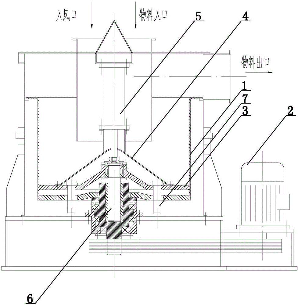
[0025] The dehydrator of this embodiment combines figure 1 , including drum 1, material inlet, material outlet, motor 2, pallet 3, hydraulic cylinder or cylinder 5, lifting shaft 6, guide rod 7, drum 1 is driven by motor 2; pallet 3 is slidably installed through guide rod 7 In the drum 1, the hydraulic cylinder or air cylinder 5 is located above the supporting plate 3, and the supporting plate 3 and the hydraulic cylinder or air cylinder 5 are connected by the lifting shaft 6. Under the pull of the hydraulic cylinder or air cylinder 5, the guide rod 7 is used as the track , the pallet 3 reciprocates up and down relative to the drum 1; the material to be processed enters the drum 1 through the material inlet with the blower, and after falling on the pallet 3, the motor 2 drives the drum 1 to rotate, and the pallet 3 passes through the guide rod While rotating with the drum, under the drive of the hydraulic cylinder or cylinder 5, the supporting plate 3 reciprocates up and down ...

Embodiment 2

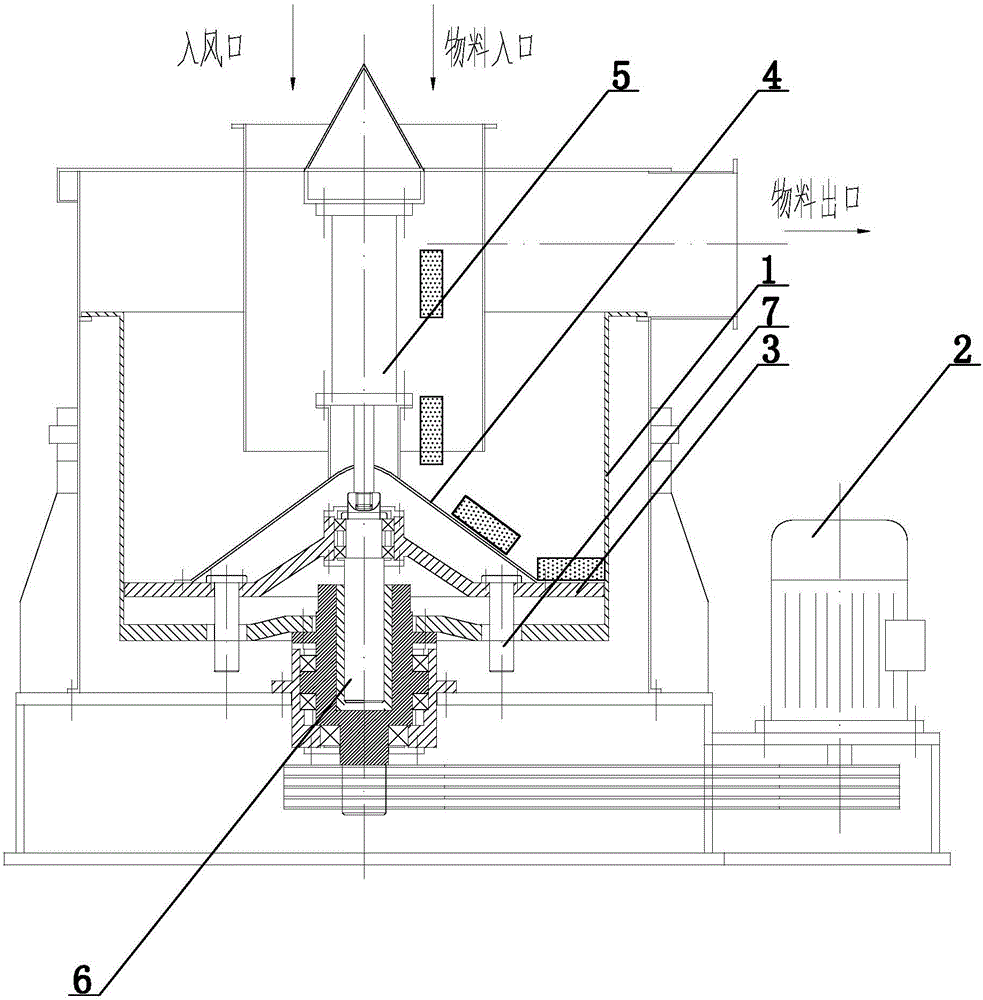
[0029] The setting and working principle of this embodiment are the same as those of Embodiment 1, the difference is that: the supporting plate 3 is provided with a cover 4, and the cover 4 is located below the material inlet. When the cover 4 is set as a structure with a high center (that is, below the material inlet, preferably directly below the material inlet) and low sides, the material falls on the cover 4 and, under its own inertial force and gravity, moves along the middle The slopes on both sides automatically slide down to both sides, effectively preventing materials from accumulating below the material inlet.

Embodiment 3

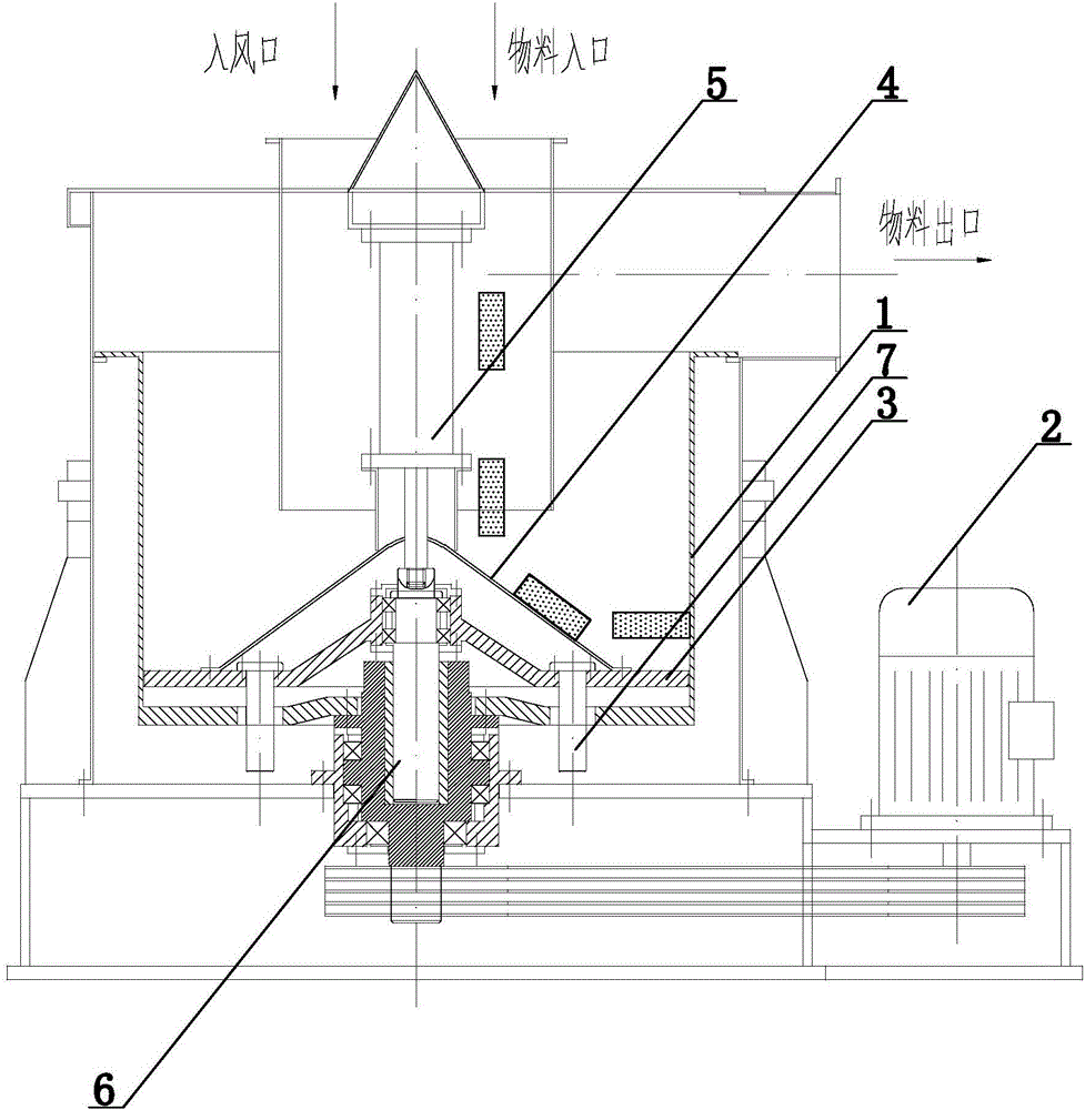
[0031] The setting and working principle of this embodiment are the same as those of Embodiment 1, the difference is that the drum 1 is driven by a motor to rotate, and is driven to reciprocate up and down by hydraulic pressure or air pressure, and the supporting plate 3 only changes its position as the drum 1 rotates. Invariably, when the drum 1 moves downward along the guide rod 7 relative to the supporting plate 3 , the material gradually moves upward until it enters the material outlet.


PUM


Abstract

The invention relates to a dehydrator and belongs to the technical field of material processing. The dehydrator comprises a drum, a material entry, a support plate and a material exit. The drum is driven by a motor, and the support plate is slidably mounted in the drum and may move up and down in the drum; material to be processed is fed into the drum by blowing air via the material entry and drops on the support plate, the motor drives the drum and the support plate to rotate together, the support plate moves up and down relative to the drum, and the material is moved up and is transferred out of the material exit. Being applied to fiber dehydration, drying and other steps, the dehydrator has the advantages of high dehydration speed, good drying uniformity, low energy consumption, low noise and the like.

Description

technical field [0001] The invention relates to a dehydrator and belongs to the technical field of material processing. Background technique [0002] Centrifugal dehydrator is a common equipment for dehydration treatment. Conventional centrifugal dehydrator removes water through the centrifugal force generated by high-speed operation. Pressed in the cylinder of the dehydrator, due to the difference in centrifugal force between the inner layer and the outer layer, it will cause uneven dehydration of the inner and outer layers; It is intermittent production, neither continuous production nor fiber dehydration effect can be guaranteed. [0003] Based on this, this application is made. Contents of the invention [0004] In view of the above-mentioned defects existing in the existing centrifugal dehydrator, the present application provides a dehydrator capable of realizing continuous processing, high dehydration efficiency and uniform dehydration. [0005] In order to achiev...

Claims


Application Information

Patent Timeline
Patent Type & Authority Applications(China)
IPC IPC(8): D06B15/10
CPCD06B15/10
Inventor 金国周俞月根曹国林金芳
Owner SHAOXING JINYU TEXITLE NEW TECH CO LTD
Why Eureka
Try Eureka