A cast-in-place beam without temporary pier support

A technology of cast-in-place beams and temporary piers, used in bridges, bridge construction, erection/assembly of bridges, etc., can solve the problems of many structural measures, complicated installation and demolition, damage to pier bodies, etc. solid effect

Active Publication Date: 2018-07-03
THE SECOND ENG CO LTD OF CHINA RAILWAY 14TH CONSTR BUREAU CO LTD +1
View PDF8 Cites 0 Cited by
  • Summary
  • Abstract
  • Description
  • Claims
  • Application Information

AI Technical Summary

Problems solved by technology

[0003] For the scaffolding in the whole hall, the disadvantages are: there are many construction measures, and the installation and dismantling are complicated; a number of temporary piers need to be built, and the requirements for the foundation are high. The latter is within the allowable range, and for the foundation range where scaffolding and scaffolding tubes are to be erected for the entire span bridge, the bearing capacity and deformation of the foundation must meet the requirements
[0005] In the above structure, the bracket must be fixed on the pier body through a certain structure. Whether it is a detachable hoop structure or a truss structure inserted into the pier body, construction needs to be carried out on the pier body, which has certain risks and is also harmful to the pier body. some damage

Method used


Image

  • A cast-in-place beam without temporary pier support
  • A cast-in-place beam without temporary pier support
  • A cast-in-place beam without temporary pier support

Examples


Embodiment 1

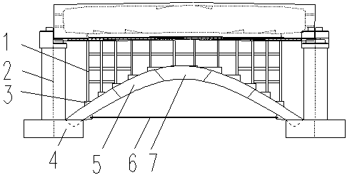
[0035] Such as figure 1 , figure 2 As shown, the invention discloses a cast-in-place beam without a temporary pier support, comprising

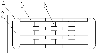
[0036] A number of arched underframes spanning in parallel between two adjacent piers and located below the cast-in-place beams;

[0037] a number of longitudinal connectors, the longitudinal spans of which are attached to all arched underframes, and

[0038] The bowl buckle support 1 stands vertically between the arched underframe and the bottom of the cast-in-place beam.

[0039] The two ends of the arched underframe are supported on the upper end surface of the pier body 2 bearing platform 4, and are fixed and spliced ​​by a number of symmetrical arch sections; each arch section has a front splicing end surface 54 and a rear splicing end surface 51, and the adjacent arch sections The space is connected through front and rear splicing end faces 54, 51. When the number of arch segments is an odd number, such as image 3 , Figure 4 As ...

Embodiment 2

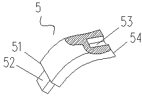
[0044] Such as image 3 , Figure 5 , Image 6 As shown, on the basis of Embodiment 1, the number of arch segments is an even number, and the front splicing end faces 54 of all arch segments have a groove 53 extending in the arch segment, and the rear splicing end face 51 has a concave groove 53 that is consistent with the adjacent arch segment. The groove 53 is embedded in the matching convex body 52, and the adjacent arch segments rely on the cooperation between the groove 53 and the convex body 52 to insert and cooperate with each other. It is the same shape as the arch segment 5 on one side of the embodiment. The arched underframe, and the requirements for the splicing of the splicing surfaces between the arch sections are not high, and it is suitable for cast-in-place beam brackets with low requirements.


PUM


Abstract

The invention relates to a cast-in-place beam scaffold without temporary piers comprising a plurality of arched underframes which in parallel and transversely stretch across the part between two adjacent pier shafts and are located below the cast-in-place beam. A plurality of longitudinal connecting frames longitudinally stretch across and are connected with all the arched underframes. Bowl-scaffolds vertically stand between the arched underframes and the bottom of the cast-in-place beam. The cast-in-place beam scaffold without temporary piers has the advantages that the ground requirement is low and the arched underframes are removable and reused with a high utilization rate by using the arched underframes instead of the original scaffolds to eliminate the need of constructing the temporary piers, the arched underframes have a good stability because the arched underframes are connected by the longitudinal connecting frames, and because of the dense distribution pattern of the arched underframes, the bowl-scaffolds are easy to be mounted on the arched underframes and no bailey beams are needed at the bottom of the cast-in-place beam thereby reducing the overall weight and benefiting the construction.

Description

technical field [0001] The invention relates to the technical field of bridge construction, in particular to a cast-in-place beam without a temporary pier support. Background technique [0002] Bracket construction refers to the construction of installing formwork on the bracket, binding the steel skeleton, and pouring concrete on site. Because its construction is relatively simple, the cost is relatively low, and it is very suitable for integral structures, it is used in bridge construction, especially in urban overpasses. It is widely used in the construction of viaducts and viaducts. At present, the most commonly used structural form of the traditional support is full-scale scaffolding, that is, using corrugated beams, columns, connectors and other components, by controlling the spacing and step distance of the steel pipe scaffolding poles, setting scissors and other structural measures, the support is set. Forming a geometrically invariant system, the biggest feature of...

Claims


Application Information

Patent Timeline
Patent Type & Authority Patents(China)
IPC IPC(8): E01D21/00
CPCE01D21/00
Inventor 高慧孙焕重周大勇于江永李强霍光明刘林孙风雪郭胜奔
Owner THE SECOND ENG CO LTD OF CHINA RAILWAY 14TH CONSTR BUREAU CO LTD
Why Eureka
Try Eureka