Device for increasing drainage volume of immersible pump

A submersible pump and flow technology, applied in water supply devices, flushing equipment with water tanks, buildings, etc., can solve the problems of wasting water, energy consumption of high-power submersible pumps, and poor toilet cleaning and flushing effects.

Inactive Publication Date: 2017-03-22
XIAMEN HUIERJIE SANITARY WARE TECH CO LTD
View PDF11 Cites 2 Cited by
  • Summary
  • Abstract
  • Description
  • Claims
  • Application Information

AI Technical Summary

Problems solved by technology

The use of high-power submersible pumps not only has the problem of energy consumption, but also the excessive space occupied by the pump body also limits the use of high-power submersible pumps.
[0003] Because of aesthetics and space-saving reasons, intelligent toilets without water tanks or ultra-low water tanks are becoming more and more popular. The current conventional flushing method for such toilets on the market is to use tap water to directly enter the toilet for washing and flushing through solenoid valve control, but tap water The biggest problem with direct flushing is that when the water pressure of the tap water pipe is lower than 0.25Mpa, sufficient water pressure and flow cannot be guaranteed, and the cleaning and flushing effect of the toilet is very poor, and the proportion of residents whose water supply pressure is lower than 0.25Mpa is still quite large Therefore, when toilet sellers sell this type of toilet, they have to come to the door in advance to measure the actual water supply pressure in the customer's home to determine the applicability
In addition, even when the water pressure of the residents’ water supply is guaranteed, due to the uncertainty of the water pressure of each user and the randomness of the water pressure fluctuation during peak water consumption, the amount of flushing water cannot be accurately set and controlled, resulting in a certain degree of waste of water

Method used


Image

  • Device for increasing drainage volume of immersible pump
  • Device for increasing drainage volume of immersible pump
  • Device for increasing drainage volume of immersible pump

Examples


Embodiment 1

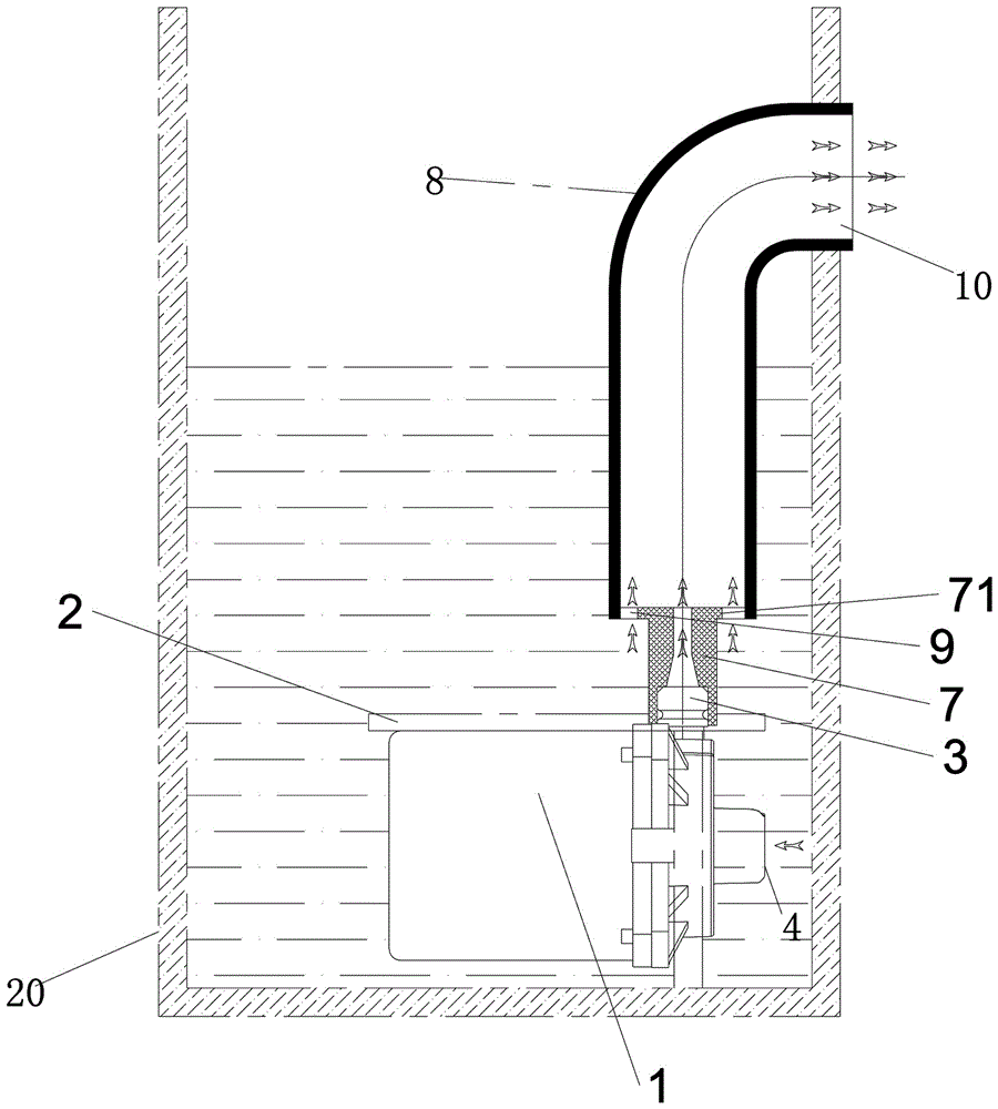
[0030] Such as Figure 4 As shown, the device for enhancing the drainage flow of the submersible pump of the present invention is applied to farmland irrigation places.

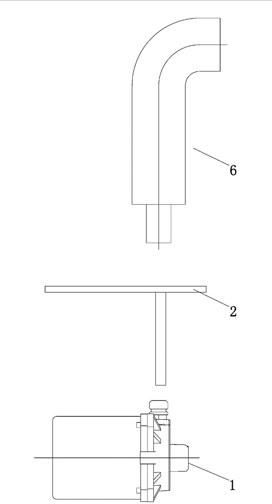
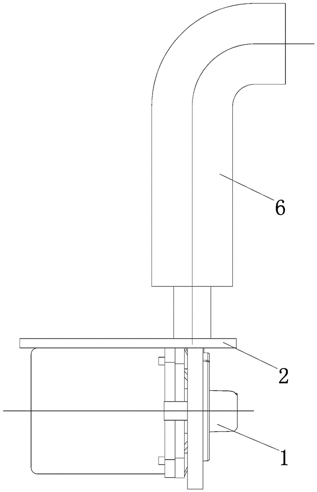
[0031] When the submersible pump 1 is started for pumping, the water in the reservoir 20 is injected into the casing inlet pipe 7 through the submersible pump outlet 3. According to the principle of Bernoulli fluid mechanics, the pressure of the fast-flowing water is stronger than that of the slow-flowing water. The pressure is low. Due to the pressure difference between the water pressure inside and outside the casing 6, the water in the reservoir 20 outside the casing 6 will also flow into the casing outlet pipe 8 through the water inlet 9 of the casing and sprayed with the submersible pump 1. After the water flows are superimposed, they are discharged from the water outlet 10 of the casing, achieving the function of using a small pump to discharge large water.

[0032] Implementation two, three and four:

[0033...


PUM


Abstract

The invention discloses a device for increasing the drainage volume of an immersible pump. The immersible pump is fixed in a reservoir. An immersible pump water inlet, an immersible pump cavity and an immersible pump water outlet of the immersible pump are lower than a working water level of the reservoir, and an opening of the immersible pump water outlet faces a sleeve. The sleeve is fixed to the upper portion of the immersible pump. The sleeve comprises a sleeve water inlet pipe and a sleeve water outlet pipe. The immersible pump water outlet is sleeved with the sleeve water inlet pipe, and the outer diameter of the top end of the sleeve water inlet pipe is smaller than the inner diameter of the water inlet end of the sleeve water outlet pipe, so that a water inlet of the sleeve is formed between the top end of the sleeve water inlet pipe and the sleeve water outlet pipe. The water outlet of the sleeve water outlet pipe is higher than a water outlet of the sleeve of the working water level of the reservoir. As for the device, through the double-superposition effect of water in the reservoir, the drainage volume of the immersible pump is greatly increased, and the purposes of saving electricity, reducing the occupied space of a pump body and reducing the cost of the immersible pump are achieved.

Description

Technical field [0001] The invention relates to a device for enhancing drainage flow, in particular to a device that uses a submersible pump to enhance drainage. Background technique [0002] In real life, people are increasingly using submersible pumps to meet various water needs. As we all know, the use of submersible pumps often choose the pump body with suitable head and drainage flow according to the actual application. In places where the drainage flow demand is large, a submersible pump of higher power is often selected to meet the drainage flow requirements. The use of high-power submersible pumps not only has the problem of energy consumption, but the excessive space occupation of the pump body also limits the use of high-power submersible pumps. [0003] Because of its beauty and space saving, intelligent toilets without water tanks or ultra-low water tanks are becoming more and more popular. The conventional method of flushing such toilets on the market is to use tap w...

Claims


Application Information

Patent Timeline
Patent Type & Authority Applications(China)
IPC IPC(8): E03D5/01
CPCE03D5/01
Inventor 郑翔骥杨斌陈明进许海烽叶惠明
Owner XIAMEN HUIERJIE SANITARY WARE TECH CO LTD
Why Eureka
Try Eureka