
Door slider with V-shaped transmission structure

A sliding door, consistent technology, applied in the direction of power control mechanism, door/window accessories, building structure, etc., can solve the problems of doors that cannot be closed, loud noise, slipping, etc., achieve maximum power increase, increase contact area, The effect of improving the slipping phenomenon

Active Publication Date: 2017-03-22
SHANGHAI YANGYANG DADUOLI HARDWARE PROD CO LTD
View PDF7 Cites 0 Cited by
  • Summary
  • Abstract
  • Description
  • Claims
  • Application Information

AI Technical Summary

Problems solved by technology

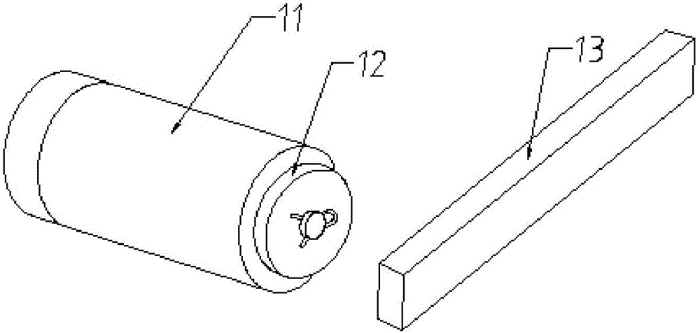
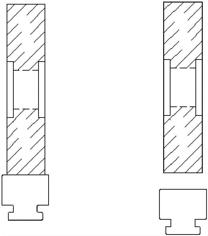
[0003] like figure 1 and 2 The shown door shifter adopts the form of cooperation between the plane wheel 12 and the plane bar 13. The motor 11 drives the plane wheel 12 to rotate, and the plane wheel 12 drives the plane bar 13 to move back and forth to realize the opening and closing of the door. When the door is heavy, it is prone to slipping, which may eventually prevent the door from closing or opening
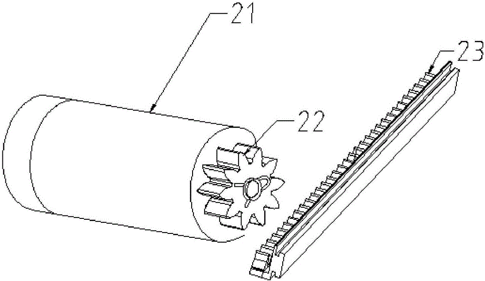
[0004] like image 3 and 4 The shown door shifter adopts the gear 22 and the gear rack 23 in the form of cooperation. The motor 21 drives the gear 22 to rotate, and the gear 22 drives the rack 23 to move back and forth, thereby realizing the opening or closing of the door. The engagement of the rack 23 makes it extremely noisy, and it is difficult to open or close the door manually during a power outage

Method used


Image

  • Door slider with V-shaped transmission structure
  • Door slider with V-shaped transmission structure
  • Door slider with V-shaped transmission structure

Examples


Embodiment Construction

[0019] The following description serves to disclose the present invention to enable those skilled in the art to carry out the present invention. The preferred embodiments described below are only examples, and those skilled in the art can devise other obvious variations.

[0020] Such as Figure 5-8 The shown door shifter includes a rotating wheel 102 arranged on a driving device 101 and a moving bar 103 arranged on the door. The driving device 101 can drive the rotating wheel 102 to rotate, and the rotating wheel 102 drives the moving bar 103 to move back and forth.

[0021] Such as Figure 5-8 As shown, the upper surface of the moving bar 103 is provided with a groove in its extending direction, and the circumferential surface of the rotating wheel 102 is formed with a protrusion matching the groove, and the protrusion is inserted into the groove, The two sides of the protrusion are in close contact with the two inner sides of the groove so that the rotating wheel 102 driv...


PUM


Abstract

The invention discloses a door slider. The door slider comprises a rotating wheel arranged on a drive device and a moving bar arranged on a door, wherein the drive device is used for driving the rotating wheel to rotate; and the rotating wheel and the moving bar realize connection through the matching between a groove and a bulge and then realize reciprocating motion of the moving bar. A transmission structure carries out power transmission through the groove and a structure matched with the groove, thus a transmission surface between the groove and the structure is expanded, then the maximum transmission force is increased, and finally the maximum transmission force between the groove and the structure is increased. Therefore, the transmission structure is capable of transmitting a heavier door without a slip phenomenon.

Description

technical field [0001] The invention belongs to the field of accessories for moving doors, in particular to a door moving device for moving doors with a V-shaped transmission structure. Background technique [0002] The use of induction doors is very common, and it also brings a lot of convenience to people's lives. At present, most of the sensor doors use sliding doors. When a moving object approaches the sliding door, the sliding door will open to both sides (linear motion, not rotation). It is mainly realized in the following two forms: [0003] Such as figure 1 and 2 The shown door shifter adopts the form of cooperation between the plane wheel 12 and the plane bar 13. The motor 11 drives the plane wheel 12 to rotate, and the plane wheel 12 drives the plane bar 13 to move back and forth to realize the opening and closing of the door. When the door is heavy, it is prone to slippage, which may eventually prevent the door from closing or opening. [0004] Such as imag...

Claims


Application Information

Patent Timeline
Patent Type & Authority Applications(China)
IPC IPC(8): E05F15/635
CPCE05F15/635
Inventor 太田益大
Owner SHANGHAI YANGYANG DADUOLI HARDWARE PROD CO LTD
Learn More