Drying box

A technology of drying box and drying chamber, which is applied in the direction of drying gas arrangement, local agitation dryer, static material dryer, etc. It can solve problems such as complex structure, affecting drying efficiency, and uneven drying.

Inactive Publication Date: 2017-03-22
常州笙绿农业科技有限公司
View PDF0 Cites 7 Cited by
  • Summary
  • Abstract
  • Description
  • Claims
  • Application Information

AI Technical Summary

Problems solved by technology

[0002] The workpiece needs to be dried in the process of production and processing to remove the moisture on the surface of the workpiece. The existing drying box has a complex structure, the drying is not uniform enough, and the humidity of the drying wind is relatively high, which affects the drying efficiency and increases the drying time.

Method used


Image

  • Drying box
  • Drying box
  • Drying box

Examples


Embodiment Construction

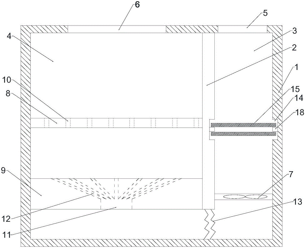
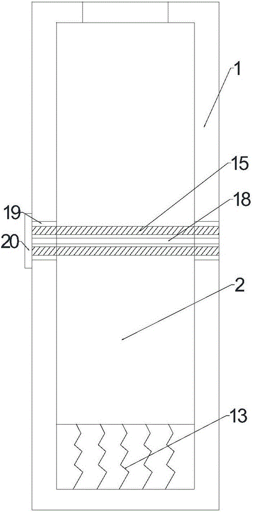
[0018] Depend on Figure 1 to Figure 3 It can be seen that a drying box of the present invention includes a box body 1 and a partition plate 2 arranged in the box body 1, the upper end of the partition plate 2 is fixedly connected with the box body 1, and the inside of the box body 1 is divided into air inlets by the partition plate 2. Chamber 3 and drying chamber 4, an air passage is formed between the lower end of the partition plate 2 and the box body 1, the air inlet chamber 3 is provided with an air inlet 5, and the drying chamber 4 is provided with an air outlet 6 , the air inlet chamber 3 is provided with a fan 7, and the drying chamber 4 is provided with a bearing plate 8 and an air deflector 9 from top to bottom, and the bearing plate 8 is provided with a plurality of ventilation holes 10, and the air deflector 9 is provided with an air inlet hole 11 and a plurality of air guide holes 12 communicating with the air inlet hole 11, the air inlet hole 11 is located below ...


PUM


Abstract

The invention relates to a drying box. The drying box comprises a box body and a partition plate arranged in the box body. The upper end of the partition plate is fixedly connected with the box body. The interior of the box body is divided into an air inlet cavity and a drying cavity by the partition plate. An air passing channel is formed between the lower end of the partition plate and the box body. An air inlet is formed in the air inlet cavity, and an air outlet is formed in the drying cavity. A draught fan is arranged in the air inlet cavity. A bearing plate and an air guiding plate are arranged in the drying cavity from top to bottom. A plurality of ventilation holes are formed in the bearing plate. An air inlet hole and a plurality of air guiding holes communicating with the air inlet hole are formed in the air guiding plate. The air inlet hole is located below the air guiding holes. The drying box is simple and reasonable in structure and convenient to operate, and drying is uniform.

Description

technical field [0001] The invention relates to a drying box. Background technique [0002] The workpiece needs to be dried in the process of production and processing to remove the moisture on the surface of the workpiece. The existing drying box has a complicated structure, and the drying is not uniform enough. The humidity of the drying wind is relatively high, which affects the drying efficiency and increases the drying time. Contents of the invention [0003] The purpose of the present invention is to provide a drying oven with uniform drying and high drying efficiency. [0004] The technical scheme that realizes the object of the present invention is as follows: [0005] A drying box, comprising a box and a partition arranged in the box, the upper end of the partition is fixedly connected with the box, the inside of the box is divided into an air inlet chamber and a drying chamber by a partition, the partition An air passage is formed between the lower end of the p...

Claims


Application Information

Patent Timeline
Patent Type & Authority Applications(China)
IPC IPC(8): F26B9/06F26B21/00F26B21/08
CPCF26B9/06F26B21/001F26B21/004F26B21/083
Inventor 应英
Owner 常州笙绿农业科技有限公司
Why Eureka
Try Eureka