
Force detection method used for substrate

A detection method and technology of strength, applied in the input/output process of data processing, instruments, electrical digital data processing and other directions, can solve the problems of strain resistance occupying a large area, complex wiring, difficult circuit layout, etc. And the effect of easy wiring, reducing the number and improving the accuracy of pressure detection

Active Publication Date: 2017-03-22
SHANTOU GOWORLD DISPLAY TECH CO LTD
View PDF10 Cites 0 Cited by
  • Summary
  • Abstract
  • Description
  • Claims
  • Application Information

AI Technical Summary

Problems solved by technology

Therefore, the strain resistance not only occupies a large area, but also has complicated wiring
[0004] However, each of the above-mentioned mechanical sensing units only realizes the pressure detection of one position. In order to realize the detection of multiple positions, it is necessary to arrange a higher-density mechanical sensing unit on the substrate, and each mechanical sensing unit includes at least four strain resistors. The bridge circuit formed will cause the arrangement of the strain resistance and the difficulty of wiring arrangement

Method used


Image

  • Force detection method used for substrate
  • Force detection method used for substrate

Examples


Embodiment 1

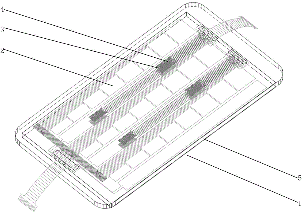
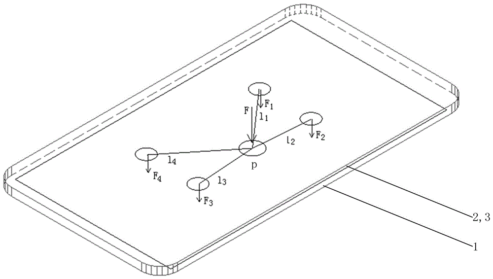
[0023] Such as figure 1 , figure 2 As shown, a force detection method for a substrate is based on a mechanical sensing board 1, the mechanical sensing board 1 includes a touch sensing layer 2 and a mechanical sensing layer 3, the mechanical sensing layer 3 includes a plurality of mechanical sensing units 4, and the mechanical sensing Unit 4 contains multiple strain resistors, including the following steps:

[0024] 1) Detecting the touch position P of the finger on the substrate 5 through the touch sensing layer 2;

[0025] 2) Through the 4 (four) mechanical sensing units 4 near the touch position P on the mechanical sensing layer 3, respectively detect the pressure transmission component f generated by the touch position P 1 , f 2 , f 3 , f 4 ;

[0026] 3) Calculate the distance l between the touch position P and each of the above-mentioned mechanical sensing units 4 1 , l 2 , l 3 , l 4 ;

[0027] 4) According to the pressure transmission component f detected by e...

Embodiment 2

[0030] In the case that other parts are the same as those in Embodiment 1, the only difference is that the calculation method of the pressing force component Fn of the touch position P is different, specifically, in step 4), the pressing force component Fn of the touch position P The specific calculation method is , where k is a lateral force transmission parameter related to the material and thickness of the substrate 5 .


PUM


Abstract

The invention discloses a force detection method used for a substrate. The method comprises the steps of detecting a touch position P, on the substrate, of a finger through a touch induction layer; detecting pressure transmission components fn generated by the touch position P through n mechanical induction units on a mechanical induction layer; calculating distances ln between the touch position P and the mechanical induction units; and calculating pressing force components Fn of the touch position P according to the pressure transmission components fn detected by the mechanical induction units and the distances ln between the touch position P and the mechanical induction units, and calculating a total pressing force F of the touch position P through the pressing force components Fn. The total pressing force F of the touch position P is obtained through the mechanical induction units around the touch position P, and the mechanical induction units do not need to be arranged in the touch position P, so that the number of mechanical strain units on a mechanical induction plate is reduced, strain resistance and circuits are arranged more easily, or the pressure detection precision is improved.

Description

technical field [0001] The invention relates to a method for detecting pressure of a glass substrate, in particular to a method for detecting the force of a substrate. Background technique [0002] By arranging the strain resistance on the substrate, the stress on the substrate, such as the pressing force of a finger on the substrate, can be detected according to the resistance change caused by the strain generated by the strain resistance when the substrate is bent under force. [0003] This kind of strain resistance is generally made as a circuitous thin film conductive wire. In order to improve the test accuracy, at least four strain resistances are set in a mechanical sensing unit (that is, a detection point) to form a bridge circuit for detection. Therefore, the strain resistance not only occupies a larger area, but also has complicated wiring. [0004] However, each of the above-mentioned mechanical sensing units only realizes the pressure detection of one position. I...

Claims


Application Information

Patent Timeline
Patent Type & Authority Applications(China)
IPC IPC(8): G06F3/041G06F3/044
CPCG06F3/0414G06F3/0416G06F3/044G06F2203/04105
Inventor 吕岳敏杨秋强郑清交彭嘉鑫彭继达陈绍源蔡泽锋
Owner SHANTOU GOWORLD DISPLAY TECH CO LTD
Learn More