
Finite element calculating method of shear deformation force of well casing

A technology of drilling casing and shear deformation, which is applied in the field of drilling and oil production, can solve the problems of costing a lot of material and financial resources, the limit of maximum shear load, and the limitation of test specifications, etc., and achieve the effect of reducing costs

Active Publication Date: 2017-03-22
TIANJIN PIPE GROUP CORP
View PDF2 Cites 15 Cited by
  • Summary
  • Abstract
  • Description
  • Claims
  • Application Information

AI Technical Summary

Problems solved by technology

However, this document can only obtain the shear deformation force of the casing through the test method. The test consumes a lot of material and financial resources, and the maximum shear load of the test equipment is limited to a certain extent, and there are also certain limitations on the test specifications.

Method used


Image

  • Finite element calculating method of shear deformation force of well casing
  • Finite element calculating method of shear deformation force of well casing
  • Finite element calculating method of shear deformation force of well casing

Examples


Embodiment 1

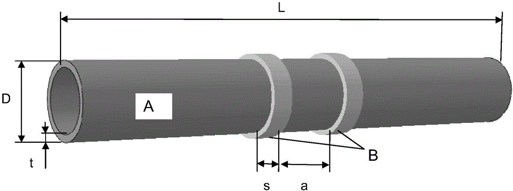
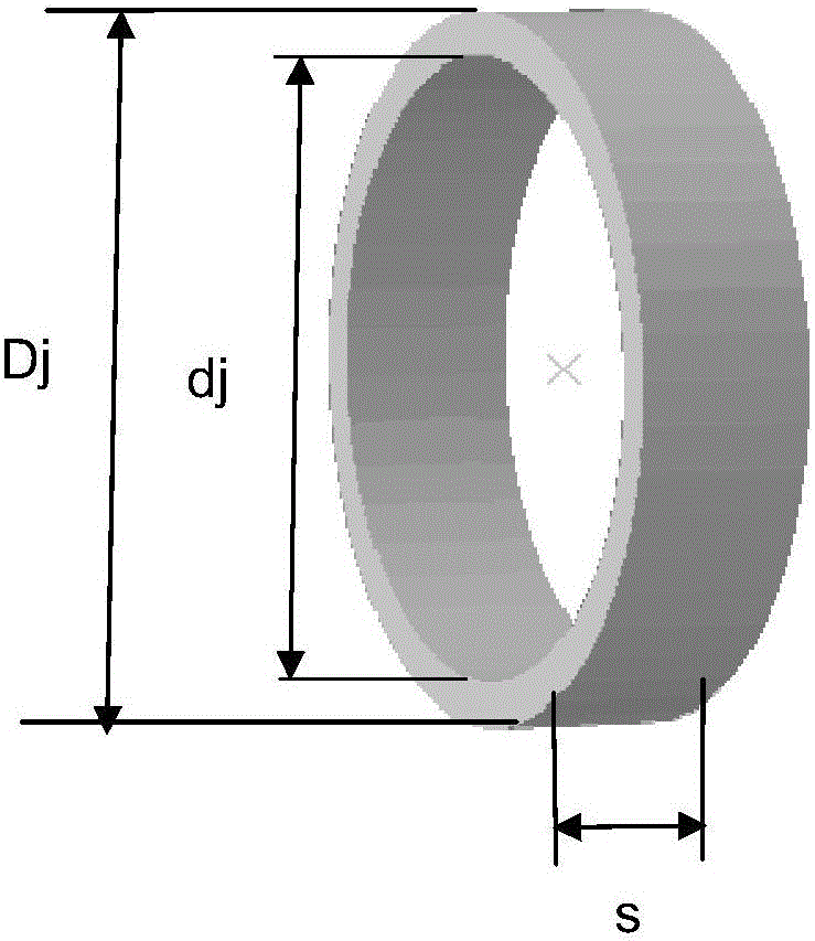
[0042] Casing specification outer diameter D=139.7mm, wall thickness t=12.7mm, steel grade Q125, elastic modulus E=206GPa, Poisson’s ratio μ=0.3, yield strength σ S =862~1034MPa, tensile strength σ b >931MPa. Modeling is carried out according to the above-mentioned finite element calculation method, the length of the pipe body is 1000mm, the width of the two shear rings is s=40mm, and the distance a=127mm. Figure 4 It is the relationship diagram between the shear force and the moving distance of the shear ring extracted by the finite element software, and the maximum value of the shear force before the sudden change can be obtained as 1625KN, so this value is the maximum shear force that the casing can withstand.

Embodiment 2

[0044] Casing specification outer diameter D=146.7mm, wall thickness t=15.9mm, steel grade TP140V, elastic modulus E=206GPa, Poisson’s ratio μ=0.3, yield strength σ S =985~1080MPa, tensile strength σ b >1034MPa. Modeling is carried out according to the above-mentioned finite element calculation method, the length of the pipe body is 1000mm, the width of the two shear rings is s=40mm, and the distance a=127mm. Through the finite element software, the maximum value of the shear force before the sudden change can be obtained as 2405KN, so this value is the maximum shear force that the casing can withstand.

Embodiment 3

[0046]Casing specification outer diameter D=177.8mm, wall thickness t=10.36mm, steel grade P110, elastic modulus E=206GPa, Poisson’s ratio μ=0.3, yield strength σ S =758~965MPa, tensile strength σ b >862MPa. Modeling is carried out according to the above-mentioned finite element calculation method, the length of the pipe body is 1000 mm, the width of the two shear rings is s=50 mm, and the distance a=127 mm. Through the finite element software, the maximum value of the shear force before the sudden change can be obtained as 1454KN, so this value is the maximum shear force that the casing can withstand.


PUM


Abstract

The invention provides a finite element calculating method of shear deformation force of a well casing. According to the method, the calculation of the shear deformation force of the well casing caused by diastrophism of stratums is simulated based on finite element software. The method comprises 11 steps. The finite element calculating method of the shear deformation force of the well casing has the advantages that through the finite element calculating method of the shear deformation force of the well casing, the morphology of a pipe body of the casing when the casing is subject to the effect of stratum diastrophism force under a well can be accurately simulated, and the size of the biggest shear and diastrophism force the pipe body can bear can also be accurately simulated; through the finite element calculating, the cost of conducting shear tests on casing pipes of well drilling and well cementation can be sharply reduced. The result of the shear force calculated through the finite element calculating method is compared with an object test, and the error is within 5%. The calculated result obtained through the finite element calculating method has an important guiding significance in the design of pipe strings of the casing pipe.

Description

technical field [0001] The invention relates to the technical field of drilling and oil production, and relates to a finite element calculation method for the shear deformation force of a drilling casing. Background technique [0002] During the drilling and extraction process, the sand produced in the oil layer will cause the formation to loosen and form cavities. The loss and slippage of formation support will produce a lateral shearing effect on the drilling and cementing casing, which will easily lead to shear damage or even complete dislocation of the casing, which will force the drilling to stop drainage, resulting in huge economic losses. loss. [0003] Chinese Patent Document No. ZL201610333516.7 discloses a drilling and cementing casing shear test system, which can apply shear force to cementing casings of different pipe diameters, and is used to simulate the relative displacement of rock formations on the cementing casing. Shearing effect. However, this document...

Claims


Application Information

Patent Timeline
Patent Type & Authority Applications(China)
IPC IPC(8): G06F17/50
CPCG06F30/23
Inventor 孙宇冉启华姚坤全陈敏范宇马勇史彬闫龙梅丽黄永智陈涛郝玉华吕春莉柳玉伟郭强张军朱海涛
Owner TIANJIN PIPE GROUP CORP
Learn More