A mechanical interlock device

An interlocking device and mechanical technology, applied in the direction of air switch components, etc., can solve the problems of occupying a large space, increasing equipment cost, and personnel danger, and achieve the effect of simple structure and increasing equipment cost

Active Publication Date: 2018-10-26
中宇博机械制造股份有限公司
View PDF4 Cites 0 Cited by
  • Summary
  • Abstract
  • Description
  • Claims
  • Application Information

AI Technical Summary

Problems solved by technology

[0003] The existing mechanical interlocking devices use the principle of leverage to close and open the isolating switch. The lever often breaks and the service life is low. The connection in the head is adsorbed, so that the isolating switch cannot be opened, and the circuit cannot be disconnected, causing danger to personnel. The existing mechanical interlocking devices work independently, so they are large in size and occupy a lot of space. Equipment cost, the existing mechanical interlocking devices use the handle to switch. When performing maintenance work, the personnel first use the handle to open the isolation switch to realize power failure, and then the personnel open the cabinet door to perform maintenance work. Forgetting to turn on the isolating switch, leading to accidents

Method used


Image

  • A mechanical interlock device
  • A mechanical interlock device
  • A mechanical interlock device

Examples


Embodiment Construction

[0023] In order to make the technical means, creative features, goals and effects achieved by the present invention easy to understand, the present invention will be further described below in conjunction with specific embodiments.

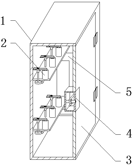
[0024] see Figure 1-Figure 5 , the present invention provides a technical solution: a mechanical interlocking device, including a switch cabinet 1, an isolating switch group 2, a cabinet door 3, a key lock structure 4 and a connecting structure 5, the front end of the switch cabinet 1 is provided with a cabinet door 3, and the cabinet The door 3 is inlaid with a key lock structure 4, the right end of the key lock structure 4 is provided with a connection structure 5, the connection structure 5 is assembled on the inner right wall of the switch cabinet 1, there are two isolating switch groups 2, and the isolating switch groups 2 are symmetrically fixed on the On the inner rear wall of the switch cabinet 1, two isolating switch groups 2 are install...


PUM


Abstract

The present invention provides a mechanical interlocking device. The device comprises a pull rod with teeth, a cylindrical bearing seat, a screw, a gear, connecting boards, an I-shaped connecting piece, a movable rod, a rotating shaft, a connecting rod, a worm I, a lock cylinder, a worm II and a worm gear. The screw is disposed in the middle at the upper end of the gear. The screw is provided with the cylindrical bearing seat. The front end of the gear is provided with the pull rod with teeth. Due to the design, the isolation switch can be turned on and off. The connecting boards are symmetrically fixed on the right end of the I-shaped connecting piece. The front end of the I-shaped connecting piece is provided with the movable rod. Two connecting boards are assembled on the upper end and the lower end of the rotating shaft. The mechanical interlocking device is simple in structure and design and has a linkage function. The left end of the connecting rod is provided with the worm I, the lower end of the worm I is provided with the worm gear, the lower end of the worm gear is provided with the worm II, and the left end of the worm II is provided with the lock cylinder. Due to the design, a cabinet and the pull rod with teeth can work simultaneously, so that the labor intensity is lowered. The mechanical interlocking device is convenient to use, has a long service life, can help reduce the cost of the device, and is highly reliable.

Description

technical field [0001] The invention relates to a mechanical interlocking device, which belongs to the field of power grid supporting equipment. Background technique [0002] The main function of the switchgear is to open and close, control and protect electrical equipment during the process of power generation, transmission, distribution and power conversion in the power system. The components in the switch cabinet are mainly composed of circuit breakers, disconnectors, load switches, operating mechanisms, transformers and various protection devices. It is mainly used in various occasions such as power plants, substations, petrochemicals, metallurgical steel rolling, light industry and textiles, factories and mines, residential quarters, and high-rise buildings. When repairing or maintaining the switchgear, when repairing the switchgear, it is necessary to disconnect the power of the overhauled equipment, even if the isolating switch is opened, so that the overhauled equip...

Claims


Application Information

Patent Timeline
Patent Type & Authority Patents(China)
IPC IPC(8): H01H31/06
CPCH01H31/06
Inventor 卢冬平王娜高利平
Owner 中宇博机械制造股份有限公司
Why Eureka
Try Eureka