
Multi-output fluorescent lamp electronic ballast

An electronic ballast, multi-channel output technology, applied in the direction of light source, electric light source, electrical components, etc., to achieve the effect of small self-loss, wide application range and low current

Inactive Publication Date: 2017-03-22
当阳市安达机电有限责任公司
View PDF0 Cites 0 Cited by
  • Summary
  • Abstract
  • Description
  • Claims
  • Application Information

AI Technical Summary

Problems solved by technology

[0003] In order to solve the above-mentioned problems existing in the existing electronic ballasts for fluorescent lamps, the task of the present invention is to provide a fully sealed multi-output electronic energy-saving and noiseless ballast for fluorescent lamps.

Method used


Image

  • Multi-output fluorescent lamp electronic ballast
  • Multi-output fluorescent lamp electronic ballast
  • Multi-output fluorescent lamp electronic ballast

Examples


Embodiment Construction

[0013] The following examples illustrate the present invention in more detail, but are not limited to the following examples as long as it falls within the scope of the present invention.

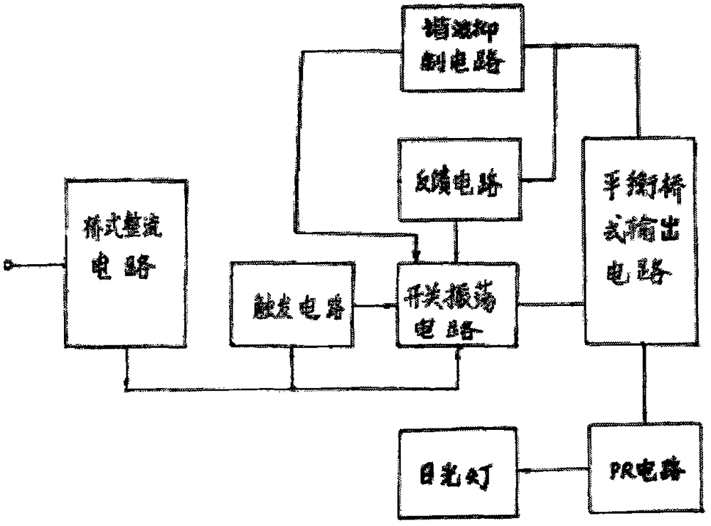
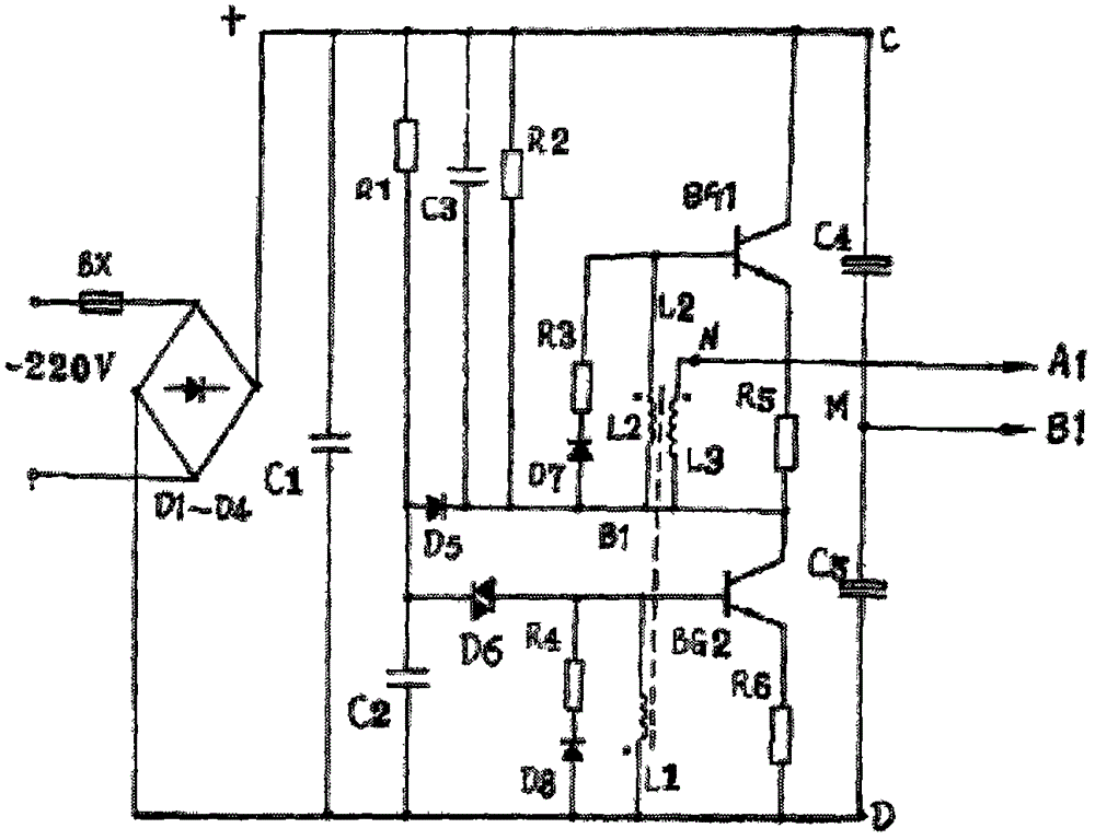
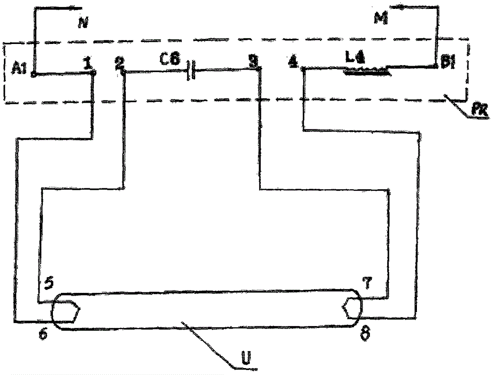
[0014] Refer to figure. 1-3. The present invention consists of rectifier diodes D1-D4 to form a full-wave rectifier, which is used as a DC working power supply for the circuit after filtering. The trigger circuit is composed of resistor R1, capacitor C2, and bidirectional diode D6, which is used to trigger switch oscillation when the circuit starts to work Circuit work. The switching oscillation circuit is composed of the switching oscillation transistor BGI.BG2 and the oscillation transformer B1. BG1.BG2 selects a high-power high-speed switching tube with a small saturation voltage drop and has a heat sink. The oscillation transformer B1 is composed of windings L1--L3. The H10 type magnetic ring is selected, and the circuit oscillation frequency is 46KHZ±10%. A balanced bridge output circ...


PUM


Abstract

The invention discloses a multi-output fluorescent lamp electronic ballast, and the electronic ballast is characterized in that the electronic ballast employs a balance bridge-type output circuit composed of a transistor and a capacitor, and a power adjustment sub-PR circuit composed of a capacitor and a choke coil, thereby enabling the electronic rectifier to be used by a plurality of fluorescent lamps; the PR is configured according to the fluorescent lamps with different powers; the on / off of any one fluorescent lamp does not affect the normal operation of other fluorescent lamps.

Description

technical field [0001] The invention relates to a fluorescent lamp electronic ballast with multiple outputs, which is an improvement to the existing fluorescent lamp electronic ballast. Background technique [0002] The existing electronic ballasts for fluorescent lamps have been developed and produced by many manufacturers in China, but they generally have the following disadvantages: first, the cost is high, and it is not easy for users to accept; The third is that the fully sealed method is not adopted, and the heat dissipation and moisture-proof performance are not good, which affects the yield and service life of the product, and it is inevitable that leakage and electric sparks will affect the safety of use; the fourth is that there are peaks in the circuit waveform, which directly affects the life of the switching oscillation transistor. . Contents of the invention [0003] In order to solve the above-mentioned problems existing in the existing electronic ballasts ...

Claims


Application Information

Patent Timeline
Patent Type & Authority Applications(China)
IPC IPC(8): H05B41/282
Inventor 谭国
Owner 当阳市安达机电有限责任公司
Learn More