Light emitter and light detector modules including vertical alignment features

A technology of vertical alignment and optical transmitter, which is applied in photometry, instrumentation, optics and other directions using electric radiation detectors. It can solve the problems of focal length change and performance degradation of optical transmitter modules, etc., and achieve improved beam focusing and operation. Good effect of promoting beam focusing

Active Publication Date: 2017-03-22
HEPTAGON MICRO OPTICS
View PDF9 Cites 5 Cited by
  • Summary
  • Abstract
  • Description
  • Claims
  • Application Information

AI Technical Summary

Problems solved by technology

The latter change may induce a change in focal length, resulting in poor performance of the optical transmitter module

Method used


Image

  • Light emitter and light detector modules including vertical alignment features
  • Light emitter and light detector modules including vertical alignment features
  • Light emitter and light detector modules including vertical alignment features

Examples


Embodiment Construction

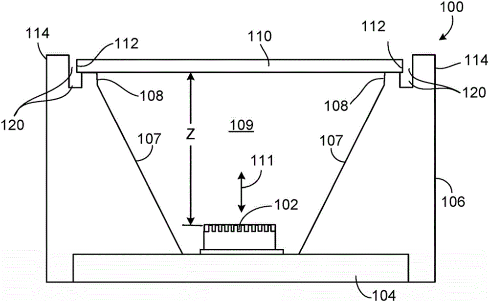
[0030] Such as Figure 1A As shown, the packaged light emitter module 100 can provide ultra-precise and stable packaging for the light emitter 102 mounted on a substrate 104, such as a lead frame. The light emitter 102 may be of the type that generates coherent, directional, spectrally defined light emission (eg, a vertical cavity surface emitting laser (VCSEL) or a laser diode). In some implementations, the light emitter 102 is operable to emit infrared (IR) light or light within the visible range of the spectrum. Since the operating temperature of the light emitter 102 can be relatively high, the lead frame or other substrate 104 can be constructed of a material such as a copper alloy that exhibits low thermal expansion. Such materials have relatively high thermal conductivity and thus may also help to provide good thermal management for the module. For example, a substrate mainly composed of copper (which has a thermal conductivity of about 260W / (mK)) can help conduct hea...


PUM


Abstract

This disclosure describes various modules that can provide ultra-precise and stable packaging for an optoelectronic device such as a light emitter or light detector. The modules include vertical alignment features that can be machined, as needed, during fabrication of the modules, to establish a precise distance between the optoelectronic device and an optical element or optical assembly disposed over the optoelectronic device.

Description

technical field [0001] The present disclosure relates to light emitter and light detector modules. Background technique [0002] Various consumer electronics and other devices include packaged light emitter modules designed for precision light projection applications. It is often necessary to control the spatial dimensions of such modules with high precision in order to precisely position the optical elements and light emitting elements at eg optimal distances. Therefore, to achieve optimal performance, the modules should have very small spatial (dimensional) and optical (eg focal length) tolerances. However, factors such as the use of adhesives in the packaged light emitter modules and other factors such as inherent manufacturing tolerances of associated support structures often exaggerate module tolerances to unacceptable levels. The above issues are also applicable to photodetector modules. [0003] For certain applications, the optical transmitter module needs to oper...

Claims


Application Information

Patent Timeline
Patent Type & Authority Applications(China)
IPC IPC(8): G02B7/02H01L27/144
CPCG02B7/02H01L27/14618H01L33/58H01L2933/0033H01L2933/0058H01L33/483G01J1/42F21S2/005G03B21/2033H01S5/02253H01S5/005H01S5/0239H01S5/183H01S5/0236H01S5/0262H01S5/028H01L27/14625H01L27/14634H01L27/1469H01L31/02325G02B7/003G03B21/142
Inventor 彼得·瑞尔马库斯·罗西丹尼尔·佩雷斯·卡莱罗马蒂亚斯·葛鲁尔摩西·多伦德米特里·巴金菲利普·布希尤
Owner HEPTAGON MICRO OPTICS
Why Eureka
Try Eureka