
Punching device with waste material recycling

A technology of scrap recycling and punching device, applied in metal processing and other directions, can solve the problems of low efficiency of carrying scrap, inconvenient scrap recycling, etc., and achieve the effect of convenient transportation and convenient movement and adjustment

Inactive Publication Date: 2017-03-29
TIANJIN YUEFENG TECH
View PDF0 Cites 1 Cited by
  • Summary
  • Abstract
  • Description
  • Claims
  • Application Information

AI Technical Summary

Problems solved by technology

The existing automatic punching machine is inconvenient to recycle the waste after punching, and the efficiency of carrying waste is low

Method used


Image

  • Punching device with waste material recycling

Examples


Embodiment Construction

[0013] The following will clearly and completely describe the technical solutions in the embodiments of the present invention with reference to the accompanying drawings in the embodiments of the present invention. Obviously, the described embodiments are only some, not all, embodiments of the present invention. Based on the embodiments of the present invention, all other embodiments obtained by persons of ordinary skill in the art without creative efforts fall within the protection scope of the present invention.

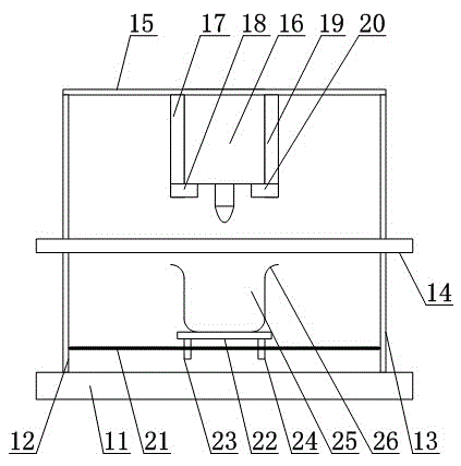
[0014] Such as figure 1 As shown, a waste recycling punching device includes a base 11, one side of the base 11 is provided with a first side plate 12, the first side plate 12 is vertically arranged, and the other side of the base 11 is provided with a second side plate. Side plate 13, the second side plate 13 is arranged vertically, is provided with stage 14 between the second side plate 13 and the first side plate 12, and object stage 14 is arranged horizontally,...


PUM


Abstract

The invention provides a punching device with waste material recycling. The device comprises a base; side plates are arranged on the base; a stage is arranged between the side plates; a top plate is arranged between the ends of the side plates; and the top plate is provided with an automatic punching machine which is arranged above the stage. A guide rod is arranged on the base; a sliding seat is arranged above the guide rod; slide blocks are arranged below the sliding seat; and the slide blocks sleeve the peripheral surface of the guide rod. A waste material recycling trolley is arranged on the sliding seat and has a storage chamber inside. According to the invention, the waste material can be quickly recycled through the waste material recycling trolley and the waste material recycling trolley can slide horizontally along the guide rod through the slide blocks, so as to facilitate the flexible movement adjustment of the waste material recycling trolley and facilitate the transportation of the waste material.

Description

technical field [0001] The invention relates to a punching device, in particular to a waste recycling punching device. Background technique [0002] The automatic punching machine is a newly developed high-precision product with high energy saving, high efficiency, stable performance and two patents - bow punching machine. The punching speed of the punching machine is 2.5 times that of similar products, which improves the punching force. The installation position of the viewfinder is fixed, and the camera is direct, which overcomes the data change caused by the movement of the viewfinder, improves the positioning accuracy of the workpiece, and greatly improves the reliability of data collection and workpiece positioning. Adopting the self-developed patent of the punch guide system and the patent of the lower die lifting device of the punching machine, this technology has the advantage of saving more than 50% of energy compared with other equipment, and greatly reduces the e...

Claims


Application Information

Patent Timeline
Patent Type & Authority Applications(China)
IPC IPC(8): B26D7/18B26F1/14
Inventor 李鹏程张志勇崔桂生周春雨许春阳
Owner TIANJIN YUEFENG TECH
Learn More