Fan mounting mechanism

A technology for installing mechanisms and fans, which is applied in the direction of pump devices, electromechanical devices, mechanical equipment, etc., and can solve problems such as inability to recycle lubricating oil and fans without installation means

Pending Publication Date: 2017-03-29
ZHENJIANG HOLY ELECTRONICS
View PDF6 Cites 0 Cited by
  • Summary
  • Abstract
  • Description
  • Claims
  • Application Information

AI Technical Summary

Problems solved by technology

But there are also some problems, such as: the oil deflecting ring is a powder sintered ring, which can only absorb the lubricating oil at the top of the oil bearing, and cannot recover the lubricating oil thrown out from the edge
In addition, the fan disclosed in the above patent does not provide a good installation method, and the working stability of the fan needs to be further improved

Method used


Image

  • Fan mounting mechanism
  • Fan mounting mechanism
  • Fan mounting mechanism

Examples


Embodiment Construction

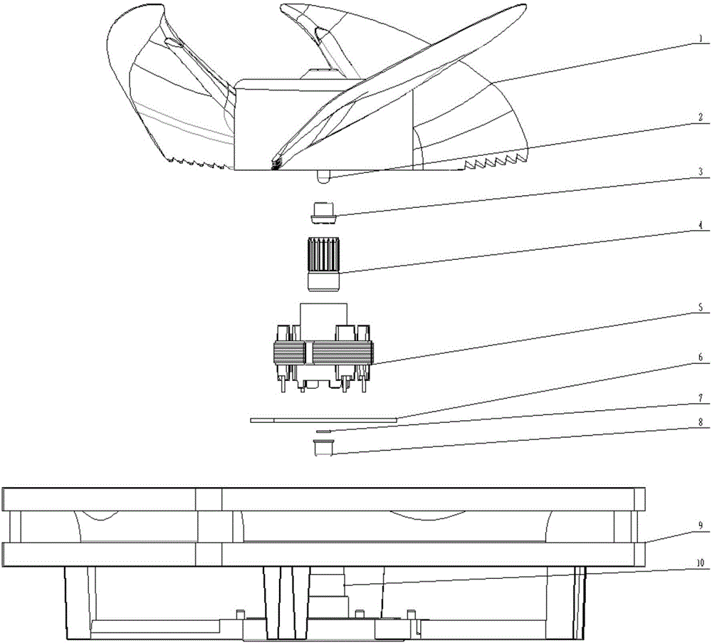
[0016] Such as figure 1 As shown, it includes a mount 9, a magnetic sleeve assembly 7, a graphite baffle 8, a stator core 5, an oil bearing 4, a limit sleeve 3, and a motor shaft 2; the mount 9 is provided with a receiving hole 10; One end of the motor shaft 2 is fixed to the blade main body 1, and passes through the limit sleeve 3 and the oil bearing 4 in turn, and can rotate relative to the limit sleeve 3 and the oil bearing 4; the limit sleeve 3 and the oil bearing 4 are installed on Inside the receiving hole 10 , the stator core 5 is set outside the receiving hole 10 and installed on the circuit board 6 ; the circuit board 6 is installed on the mounting seat 9 .

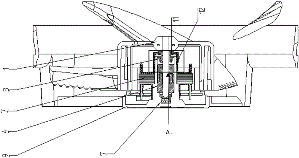
[0017] Such as figure 2 with 3 As shown, the stator core 5 is provided with an opening above the receiving hole 10, and the cross-sectional shape of the opening is trapezoidal.

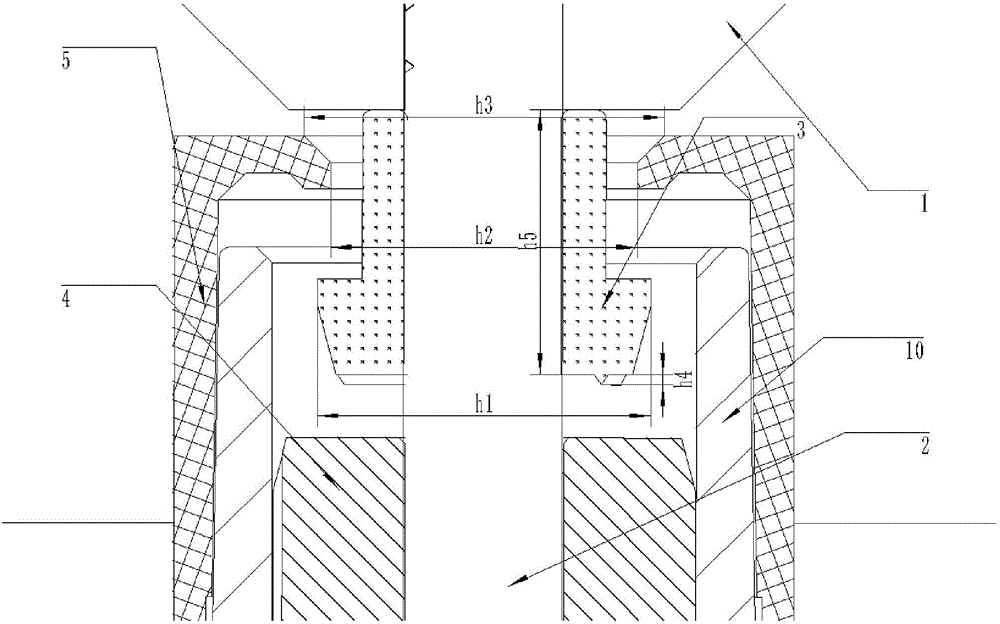
[0018] Such as Figure 4 As shown, the limit sleeve 3 is an inverted T-shaped structure, and the lower end of the limit sleeve 3 i...


PUM


Abstract

The invention provides a fan mounting mechanism. The fan mounting mechanism comprises a mounting base, a magnetic sleeve assembly, a graphite separation blade, a stator core, an oil-containing bearing and a motor shaft, wherein the motor shaft is arranged in the oil-containing bearing, and can rotate relative to the bearing; one end of the motor shaft is fixed to a blade main body; the oil-containing bearing is nested in the stator core; the stator core is arranged on a circuit board; a limiting sleeve is arranged between the oil-containing bearing and the blade main body; the mounting base is provided with an accommodating hole; the magnetic sleeve assembly is arranged in the accommodating hole. By adopting the fan mounting mechanism, self-circulation of lubricating oil and further fixing of a fan are realized.

Description

technical field [0001] The invention relates to a mounting mechanism, in particular to a fan mounting mechanism. Background technique [0002] Axial fans are widely used in heat dissipation of machines such as laptops and refrigerators. In addition to having good low-noise characteristics, it also needs to be able to work stably for a long time. There are two main factors that affect the service life of the fan: the circulation effect of the lubricating oil and the smoothness of the fan when it is working. Patent No.: 200710077333.4 discloses a fan, the main improvement of which is to add an oil deflector ring above the oil bearing to realize the self-circulation of lubricating oil. But there are also some problems, such as: the oil deflecting ring is a powder sintered ring, which can only absorb the lubricating oil at the top of the oil bearing, and cannot recover the lubricating oil thrown out from the edge. In addition, the fan disclosed in the above patent does not pr...

Claims


Application Information

Patent Timeline
IPC IPC(8): F04D25/08F04D29/64F04D29/063H02K5/16
CPCH02K5/16F04D25/08F04D29/063F04D29/644
Inventor 段宏扣李远培陈秀山宦文英
Owner ZHENJIANG HOLY ELECTRONICS
Why Eureka
Try Eureka