

Connecting structure for mortise-tenon connecting components and rolled-groove leaf-spring corner protector
A technology for connecting components and connecting structures, which is applied in the connection of rods, connecting components, mechanical equipment, etc. It can solve the problems of limited selection range and inability to adjust the furniture structure, and achieve the effect of convenient and simple disassembly and improvement of overall stability
- Summary
- Abstract
- Description
- Claims
- Application Information
AI Technical Summary
Problems solved by technology
Method used
Image

Examples
Embodiment Construction
[0018] The technical solutions claimed in the present invention will be further described in detail in conjunction with the accompanying drawings and specific embodiments.
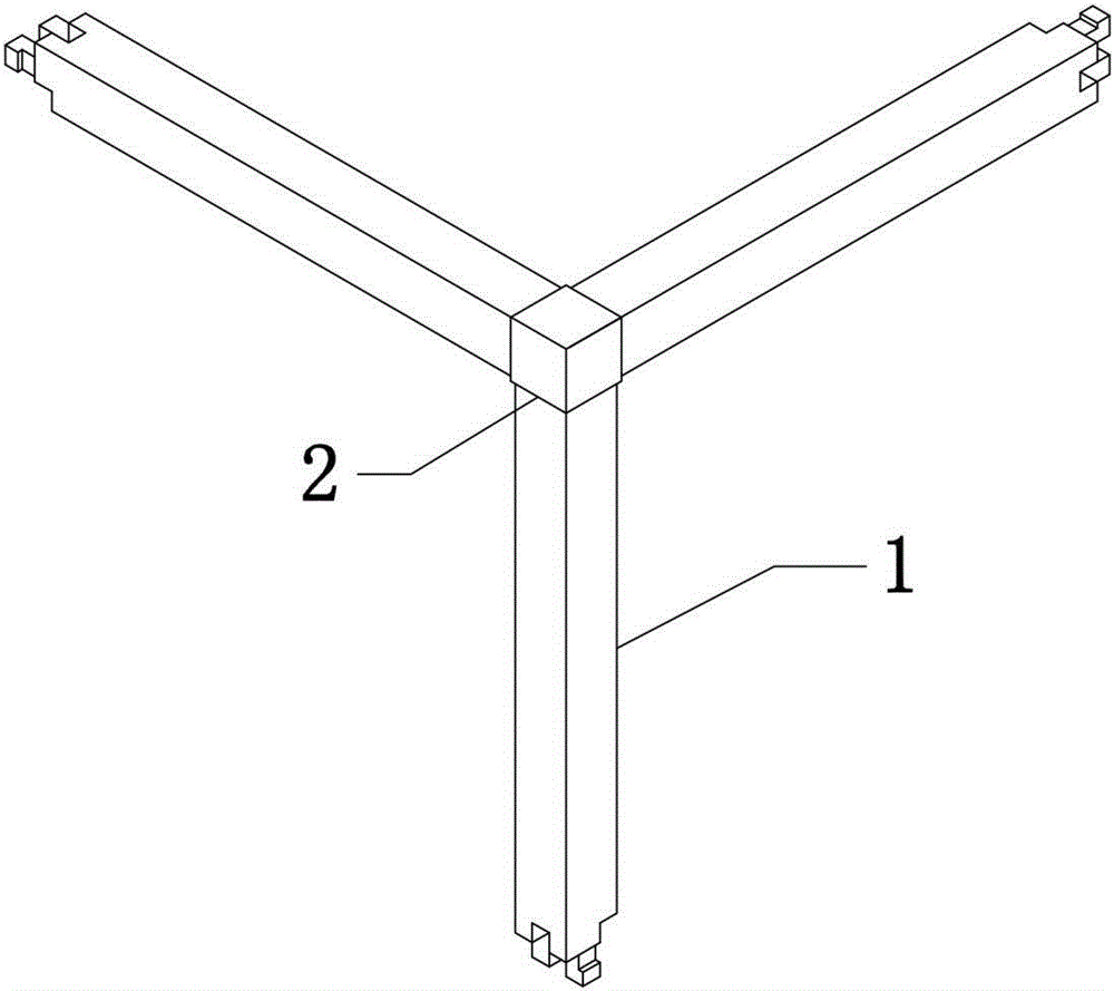
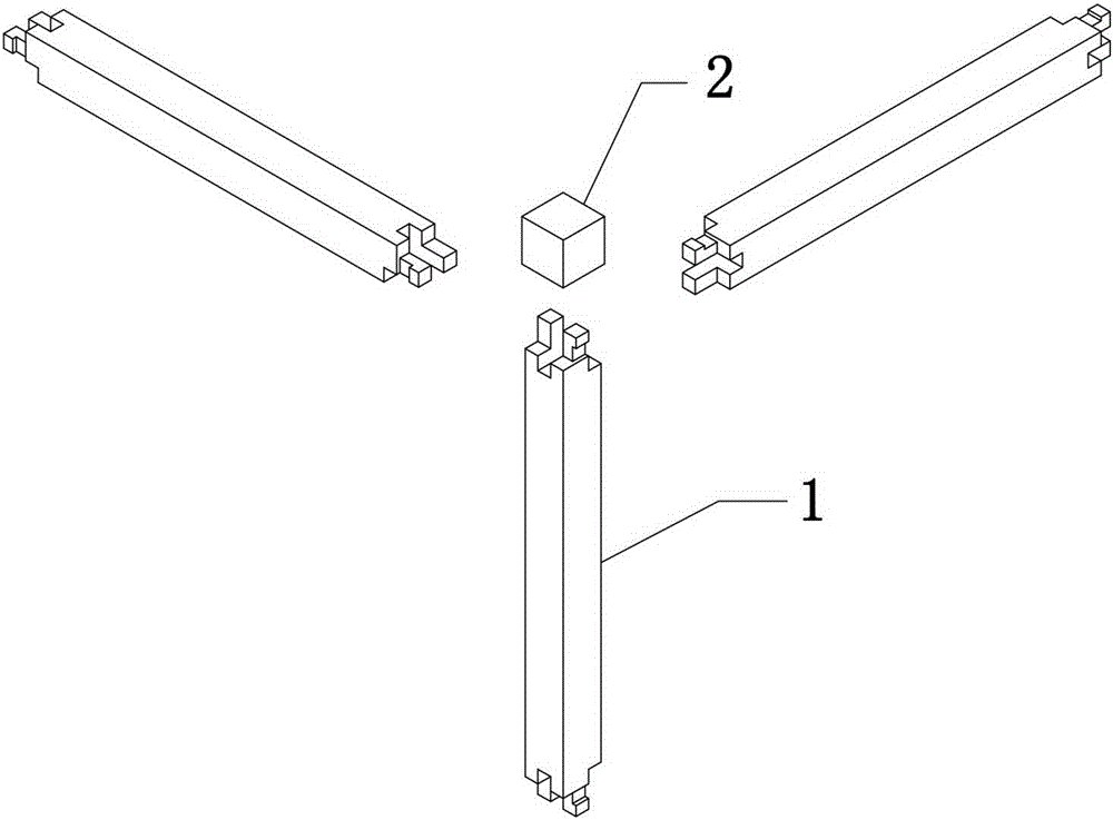
[0019] See attached Figure 1-2 As shown, the connection structure between the mortise and tenon joint assembly and the grooved shrapnel angle in this embodiment is composed of three mortise and tenon joint assemblies 1 and one grooved shrapnel angle 2 that are jointly connected.
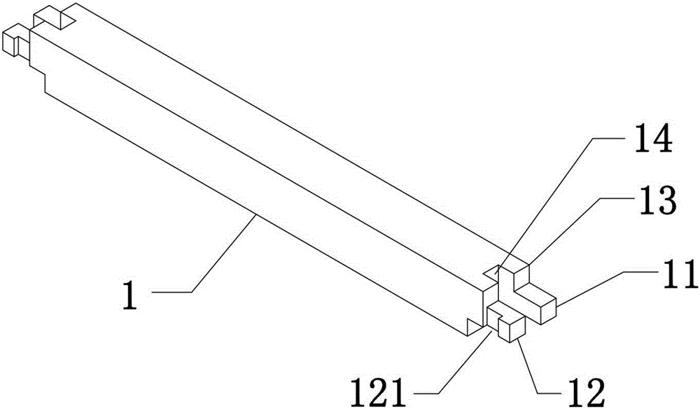
[0020] See attached image 3 As shown, the mortise-and-tenon connection assembly 1 is a long-axis structure, and a first long tenon 11 and a second long tenon 12 that are symmetrical to each other are respectively formed on two opposite sides of the end surface of the tenon-tenon connection 1, wherein the second long tenon A notch 121 is reserved on the outer side of 12, and two mutually symmetrical short tenons 13 are respectively formed on the two opposite sides. The intervals between the first long tenon 11 and the second l...
PUM
 Abstract
Description
Claims
Application Information