
Impedance detection method for charging line of load, chip, and mobile terminal

A charging line, impedance detection technology, applied in the direction of measuring resistance/reactance/impedance, measuring device, measuring electrical variables, etc., can solve the problems of user personal or property loss, odor, no impedance detection function, etc.

Active Publication Date: 2017-03-29
MEIZU TECH CO LTD
View PDF9 Cites 17 Cited by
  • Summary
  • Abstract
  • Description
  • Claims
  • Application Information

AI Technical Summary

Problems solved by technology

[0003] In addition, due to the wear and tear of the charging port, the connector impedance becomes larger. If this impedance change cannot be detected and the charging is not controlled, the heat generation at this position will increase as the square multiple of the current, and the heat accumulation will cause damage to cables and mobile terminals. The charging interface of the charging port is overheated and deformed, emits a peculiar smell, and loses its own functions. If the consequences are serious, the user may be burned due to heat transfer, and the property may be burned, which may cause personal or property damage to the user.
[0004] There is no impedance detection function in the existing mobile terminals

Method used


Image

  • Impedance detection method for charging line of load, chip, and mobile terminal
  • Impedance detection method for charging line of load, chip, and mobile terminal
  • Impedance detection method for charging line of load, chip, and mobile terminal

Examples


Embodiment 1

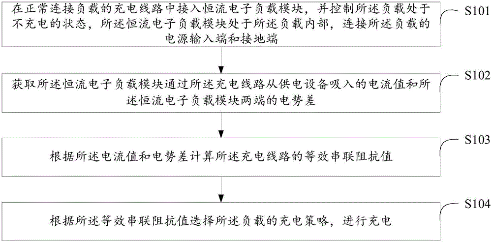
[0043] see figure 1 , figure 1 It is a method flowchart of the first embodiment of the impedance detection method of the charging line of the load provided by the present invention. In the first embodiment, the impedance detection method of the charging line of the load includes:

[0044] S101. Connect a constant current electronic load module to the charging line normally connected to the load, and control the load to be in a non-charging state. The constant current electronic load module is inside the load and connected to the power input terminal of the load. and ground terminal.

[0045]The above-mentioned loads are mobile terminals, such as mobile phones, mp3 players, notebook computers, smart watches, smart bracelets, tablet computers, portable game consoles, etc. When the mobile terminal is charged, generally a power adapter or a mobile power supply is connected to the charging interface of the mobile terminal through a charging cable for charging. The impedance detec...

Embodiment 2

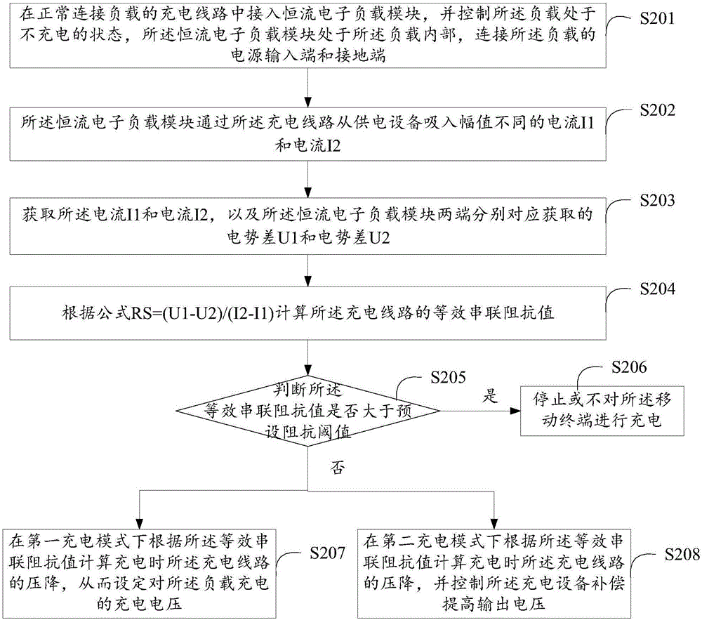
[0054] see figure 2 , figure 2 It is a method flowchart of the second embodiment of the impedance detection method of the charging line of the load provided by the present invention. In the second embodiment, the impedance detection method of the charging line of the load includes:

[0055] S201. Connect a constant current electronic load module to the charging line normally connected to the load, and control the load to be in a non-charging state. The constant current electronic load module is inside the load and connected to the power input terminal of the load. and ground terminal.

[0056] The load refers to the above-mentioned mobile terminal. After the charging line is connected normally, the impedance of the charging line is calculated first, and the terminal is not charged when calculating the impedance of the charging line. At the same time, the impedance detection method of the charging line can also be applied to the charging process of the mobile terminal. In t...

Embodiment 3

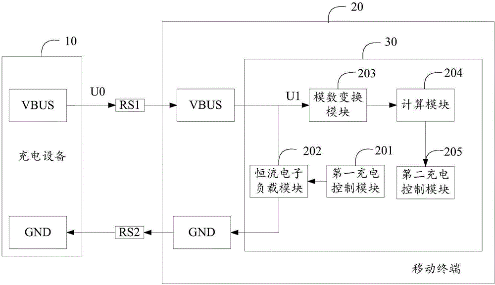
[0071] see image 3 , image 3 It is a schematic structural diagram of the first embodiment of the impedance detection chip 30 of the charging line of the load provided by the present invention. Please refer to the method embodiment for the parts not described in detail in the chip embodiment. In the third embodiment, the impedance detection chip 30 of the charging circuit of the load is used to be arranged in the load and connected to the power input terminal (VBUS) and the ground terminal (GND) of the load, and the chip includes:

[0072] The first charging control module 201 is configured to detect whether the load 20 is normally connected to the charging circuit, and control the load 20 to be in a non-charging state when it is detected that the load 20 is normally connected to the charging circuit. When detecting the equivalent series impedance of the charging line, the load 20 is not charged, the equivalent series impedance is RS=R1+R2, and the load is the above-mentione...


PUM


Abstract

The invention discloses an impedance detection method for a charging line, a chip and a terminal. A current-constant electronic load module is connected to the charging line of a normally connected load, the load is controlled to be in a no-charging state, a value of currents that the current-constant electronic load module takes from a charging device via a charging line and a potential difference between the two ends of the current-constant electronic load module are obtained, an equivalent serial impedance value of the charging line is calculated according to the current value and the potential difference, a charging strategy of the load is selected according to the equivalent serial impedance value, and charging is carried out. When the load is in the no-charging state, a power input interface of the load is connected to the current-constant electronic load module, the current-constant electronic load module take currents from the charging device via the charging line, the potential difference between the two ends of the current-constant electronic load module is detected and obtained, the impedance of the charging line can be calculated effectively, the load selects the charging strategy according to the impedance, and the charging efficiency and effect are improved.

Description

technical field [0001] The invention relates to the field of charging of mobile terminals, in particular to a method for detecting impedance of a charging circuit of a load, a chip and a terminal. Background technique [0002] At present, the charging current of mobile terminals has become larger, and the charging methods have become diverse, mainly including low-voltage fast charging and high-voltage fast charging. However, due to the variety of charging cables used by users, and the MICRO USB or type C interface is generally used as the charging input port for charging equipment, as the number of plugging increases, it is easy to cause wear and tear on the pins of the cable connector port, and the contact impedance becomes larger, making the impedance on the charging line unpredictable and affecting the implementation of a good charging strategy. For example, setting the appropriate charging voltage and charging current can achieve the purpose of short charging time, high...

Claims


Application Information

Patent Timeline
IPC IPC(8): G01R27/08
CPCG01R27/08
Inventor 易鹏程黄昌松
Owner MEIZU TECH CO LTD
Learn More