Flying probe test machine light source system and control method thereof

The technology of a flying probe testing machine and light source system, which is applied in the field of flying probe testing machine light source system and its control, can solve the problems of high economic cost and the difficulty of light source system meeting the requirements of machines with high test accuracy, and achieve reliable and effective work. Facilitating image recognition and reducing manufacturing costs

Active Publication Date: 2017-03-29
HANS CNC SCI & TECH
View PDF4 Cites 0 Cited by
  • Summary
  • Abstract
  • Description
  • Claims
  • Application Information

AI Technical Summary

Problems solved by technology

In the existing flying probe testing machine, the light source system with simple functions is difficult to meet the requirements of high testing precision machines. If it needs to be met, it will cost a higher economic cost

Method used


Image

  • Flying probe test machine light source system and control method thereof
  • Flying probe test machine light source system and control method thereof
  • Flying probe test machine light source system and control method thereof

Examples


Embodiment Construction

[0046] In order to facilitate the understanding of the present invention, the present invention will be described more fully below with reference to the associated drawings. Preferred embodiments of the invention are shown in the accompanying drawings. However, the present invention can be embodied in many different forms and is not limited to the embodiments described herein. On the contrary, these embodiments are provided to make the understanding of the disclosure of the present invention more thorough and comprehensive.

[0047] Unless otherwise defined, all technical and scientific terms used herein have the same meaning as commonly understood by one of ordinary skill in the technical field of the invention. The terms used herein in the description of the present invention are for the purpose of describing specific embodiments only, and are not intended to limit the present invention.

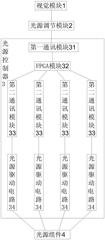
[0048] refer to figure 1 As shown, a flying probe testing machine light source syst...


PUM


Abstract

The invention discloses a flying probe test machine light source system. The system comprises a vision module, a light source adjustment module, a light source controller and a light source assembly, wherein the vision module is connected with the light source controller through the light source adjustment module, and the light source controller is also connected with a light source on the light source assembly. Adjustment of light source on-off degrees in multiple directions can be carried out, light distribution of a pad on a flying probe test machine PCB to be tested is enabled to be more uniform, image identification is facilitated, the imaging quality is improved, and the test precision of the flying probe test machine is improved. At the same time, automatic light source adjustment helps to obtain better imaging quality, manual participation is unnecessary, the manual adjustment mode is quite simple, and the operation convenience is greatly improved. Besides, the light source system is relatively simple in structure and reliable in work, decreases the manufacturing cost of the light source system and also reduces the development time of the light source system.

Description

technical field [0001] The present invention relates to the technical field of flying probe testing machine vision, and more specifically relates to a flying probe testing machine light source system and a control method thereof. Background technique [0002] The flying probe testing machine obtains and calculates the relevant position of the PCB solder joint through the machine vision system, and installs a motor-driven probe on the X-Y axis that can move independently and quickly, using the controllable movement of the probe in the Z direction and fixing it on the A device that makes contact with the solder joints of a printed circuit board (PCB) on a machine and makes electrical measurements. The vision system is the eyes of the flying probe testing machine. The test position of the pad measuring point needs to be positioned and calculated by the vision system before it can guide the motion control system to perform related actions. The recognition accuracy of the vision ...

Claims


Application Information

Patent Timeline
Patent Type & Authority Applications(China)
IPC IPC(8): H05B37/02G01R31/28
CPCY02B20/40
Inventor 欧阳书琴谭艳萍王星翟学涛杨朝辉高云峰
Owner HANS CNC SCI & TECH
Why Eureka
Try Eureka