Manufacturing method for thin-specification hot-rolled strip steel

A technology of hot-rolled strip steel and manufacturing method, which is applied in metal rolling, manufacturing tools, metal rolling, etc., can solve the problems of poor surface quality and high power consumption of production lines, improve product surface quality, and increase rolling kilometers. Counting and prolonging the effect of roller changing cycle

Active Publication Date: 2017-04-05
NORTHEASTERN UNIV
View PDF7 Cites 32 Cited by
  • Summary
  • Abstract
  • Description
  • Claims
  • Application Information

AI Technical Summary

Benefits of technology

This patented method allows for better use of waste heat from continuously cast steel plates during manufacturing compared to traditional methods like quench water coolers or oil bath systems used by other industries such as aluminium industry. Additionally, this process helps reduce power usage while maintaining high efficiency levels through efficient removal of scale on surfaces produced after processing.

Problems solved by technology

This patented technical problem addressed in this patents relates to improving the efficiency and effectiveness of producing thin-grained hot-rolling sheet steels from existing methods such as direct connection between the continucasting machine and two stands or indirectly connecting them together without requiring fast speeds. Additionally, there may also exist issues related to energy usage during the rolling step when inducing magnetic field lines within the material being processed.

Method used


Image

  • Manufacturing method for thin-specification hot-rolled strip steel

Examples


Embodiment

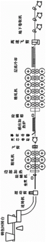
[0028] The process layout diagram of the thin-gauge steel strip production process of the present invention is as figure 1 shown. The specific implementation steps are as follows:

[0029] (1) The qualified molten steel produced in the steelmaking workshop is transported to the continuous casting workshop, and is hoisted by a crane to the ladle seat of the ladle turret, and the ladle turret rotates half a circle to the pouring position before pouring.

[0030] (2) After the casting starts, the casting speed of the continuous casting machine is gradually increased to 6.0m / min, the thickness of the continuous casting slab at the mold outlet is 90-110mm, the sector section is pressed down by 10mm, and the thickness of the casting slab at the exit of the continuous casting machine is 80-100mm. After the casting speed stabilizes, the surface temperature of the slab at the exit of the continuous casting machine is 1050-1150°C, and the temperature of the core of the slab is 1300-140...


PUM

PropertyMeasurementUnit
Thicknessaaaaaaaaaa

Abstract

The invention discloses a manufacturing method for thin-specification hot-rolled strip steel. The manufacturing method is characterized in that a single-machine uniflow thin slab continuous casting machine is directly connected with a rolling mill. The manufacturing method comprises the steps of steel-making, continuous casting, swing type shearing, steel pushing, descaling, side heating, unit rough rolling, fly shearing, coreless coiling, induction heating, descaling, unit finish rolling, strip steel cooling, shearing, coiling, coil discharging, bundling, coil transporting, weighing and marking, transporting and storing. The manufacturing method adopts an endless rolling process or a single-billet rolling process. A temperature of casting billet at an outlet of the continuous casting machine is higher than that of an ESP production line by 100-150 DEG C, so that a utilization rate of waste heat of continuously cast billet is increased, and energy consumption is reduced; compared with the ESP production line, the manufacturing method has the advantages that: swing type shears and a steel pushing roller way are migrated to the front of a roughing mill, so that distances from the swing type shears and the steel pushing roller way to a middle roller way are shortened after rough milling, temperature drop of intermediate billets is reduced, induction heat compensation amount is reduced, and a roll of the roughing mill can be prevented from generating thermal cracks. A descaling device is arranged at an inlet of the roughing mill, and a finish rolling unit adopts an online heating preparation technology and an online quick roll-changing technology, so that surface quality of products is effectively improved.

Description


Claims


Application Information

Patent Timeline
Owner NORTHEASTERN UNIV
Why Eureka
Try Eureka