Engine rear suspension combination module and automobile front subframe assembly assembly

A front subframe and rear suspension technology, applied in the direction of power plant, transportation and packaging, vehicle parts, etc., can solve the problems of affecting the safety performance of the whole vehicle, high torsional rigidity, increasing the development cycle and development cost of the vehicle, and achieving The effect of reducing the development cycle and development cost

Active Publication Date: 2019-09-03
GREAT WALL MOTOR CO LTD
View PDF5 Cites 0 Cited by
  • Summary
  • Abstract
  • Description
  • Claims
  • Application Information

AI Technical Summary

Problems solved by technology

The three-point suspension has the best motion compliance, because three points determine a plane, which is not affected by the deformation of the frame, and the natural frequency is low, and the effect of anti-torsional vibration is good; the four-point suspension has good stability and can overcome large Torque reaction force, but the torsional stiffness is relatively large, which is not conducive to isolating low-frequency vibration
[0004] The existing automobile front sub-frame assembly assembly can only be assembled into a three-point mount or a four-point mount. When the mounted engine or the supporting four-point suspension front sub-frame does not match the installed three-point suspension engine, the original front sub-frame needs to be refitted due to the difference in the rear suspension structure and the position of the rear suspension. Developed a new front sub-frame, in order to meet the impact of rigidity, strength, and collision collapse, it is necessary to repeatedly modify the structure of the front sub-frame itself, which increases the development cycle and development cost of the car, and also affects the safety performance of the vehicle

Method used


Image

  • Engine rear suspension combination module and automobile front subframe assembly assembly
  • Engine rear suspension combination module and automobile front subframe assembly assembly
  • Engine rear suspension combination module and automobile front subframe assembly assembly

Examples


Embodiment Construction

[0055] It should be noted that, in the case of no conflict, the embodiments of the present invention and the features in the embodiments can be combined with each other.

[0056] The present invention will be described in detail below with reference to the accompanying drawings and examples.

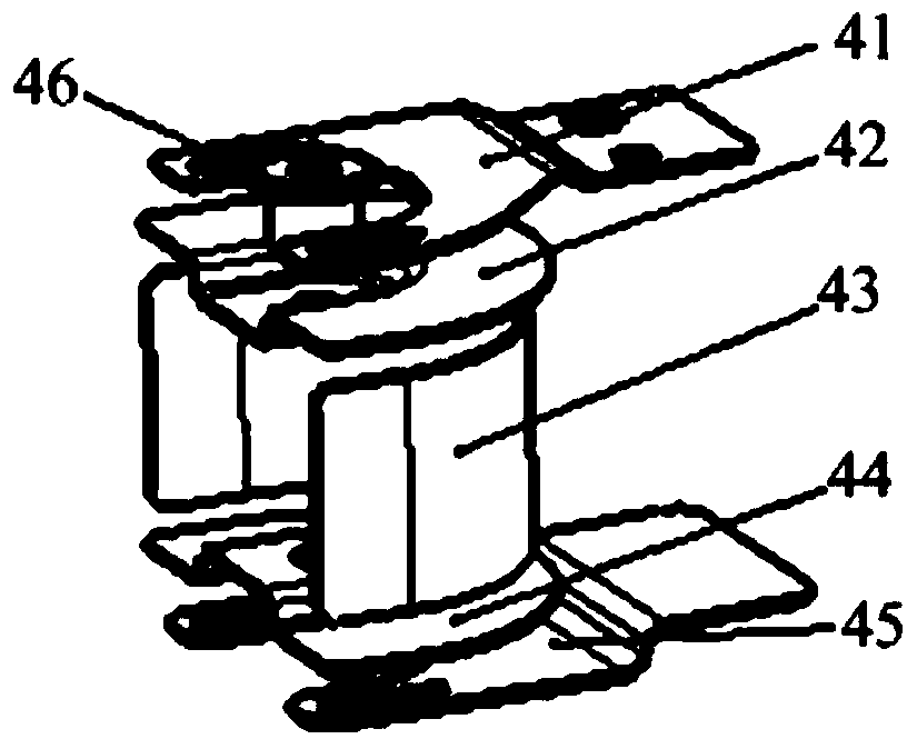
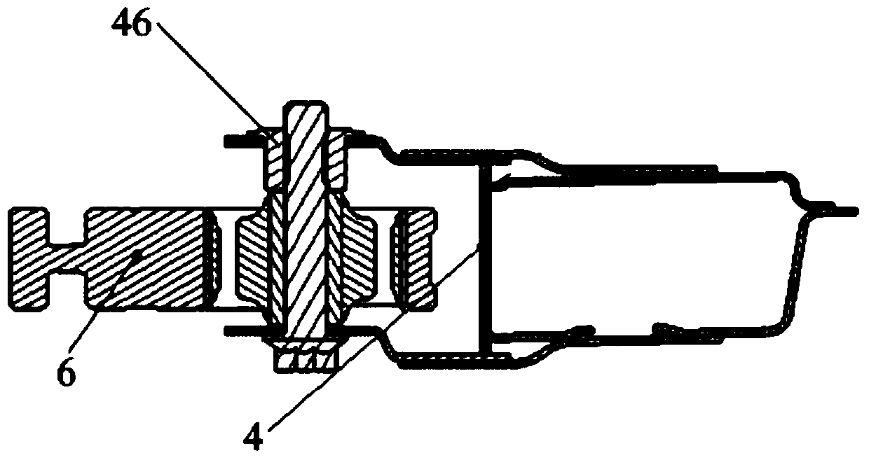
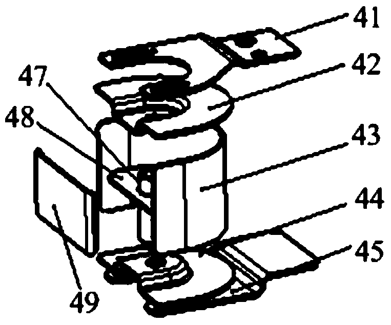
[0057] Please refer to the attached Figure 1-3 , the engine rear suspension combination module 4 provided by the embodiment of the present invention includes: a module body for being arranged on the rear cross member 3 of the front subframe of the automobile in the overlapping area of ​​the three-point rear suspension and the four-point rear suspension; The first connection part connected to the engine rear suspension tie rod 6, the first connection part is used to be arranged on the module body; the second connection part that can be connected with the four-point engine rear suspension bracket, the second connection part is used to be arranged on the on the module body.

[0058] It s...


PUM


Abstract

The invention provides an engine rear mounting combined module and an automobile front auxiliary frame assembling assembly. The engine rear mounting combined module is formed by a module body arranged in an overlapped area between a three-point rear and a four-point rear mounting of a back transverse beam of the automobile front auxiliary frame, a first connection part connected with a three-point engine rear mounting pull rod and a second connection part connected with a four-point engine rear mounting support, wherein the first connection part is arranged on the module body; and the second connection part is arranged on the module body. The engine rear mounting combined module is arranged in the overlapped area between the three-point rear and the four-point rear mounting of the back transverse beam; by the use of the first connection part, rear mounting matching with the four-point mounting engine is achieved; by the use of the second connection part, rear mounting matching with the three-point mounting engine is achieved; and re-development of the whole front auxiliary frame can be avoided, so developing period and cost can be reduced.

Description

technical field [0001] The invention relates to the technical field of automobile production and manufacturing, in particular to an engine rear suspension assembly module and an automobile front subframe assembly assembly having the above-mentioned engine rear suspension assembly module. Background technique [0002] In the automotive system, the powertrain composed of the engine, clutch and gearbox is installed on the chassis of the car through the suspension bracket. The suspension bracket has a good vibration isolation effect, which can not only reduce the vibration and shock from the engine, but also reduce Vibration and shock on the road surface. [0003] For a car with a front engine, the left and right mounting points of the engine are arranged on the body, and the front and rear mounting points are arranged on the front sub-frame assembly. The engine is divided into three-point type and four-point type according to the number of mounts. The three-point type generall...

Claims


Application Information

Patent Timeline
Patent Type & Authority Patents(China)
IPC IPC(8): B60K5/12B62D21/02
Inventor 李麒康存祥裴玉于洋李晓娟黄美娜
Owner GREAT WALL MOTOR CO LTD
Why Eureka
Try Eureka