Speed change gear structure, transmission and vehicle

A technology for shifting gears and transmissions, applied in the field of shifting gears, can solve the problems of reducing abnormal idle noise, disadvantage, increase in transmission weight, volume and cost, and achieve the effect of weight reduction and cost optimization.

Inactive Publication Date: 2017-04-05
GREAT WALL MOTOR CO LTD
View PDF5 Cites 1 Cited by
  • Summary
  • Abstract
  • Description
  • Claims
  • Application Information

AI Technical Summary

Problems solved by technology

[0004] However, in the existing 6-speed transmission structure, each pair of gear pairs transmits a single power flow, that is, a gear, and different gears require different gear pairs to transmit power flow, which cannot maximize the effect of each gear; in addition , the increase of the gear position needs to incr

Method used


Image

  • Speed change gear structure, transmission and vehicle
  • Speed change gear structure, transmission and vehicle

Examples


Embodiment 1

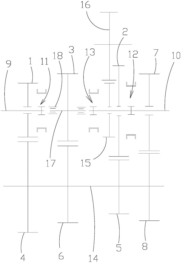
[0027] Such as figure 2 As shown, the transmission gear structure of the first embodiment of the present invention includes an input shaft 9, an output shaft 10, an intermediate shaft 14, three gear transmission pairs and three synchronizers, wherein the input shaft 9 and the output shaft 10 are coaxially spaced apart The intermediate shaft 14 is arranged parallel to the input shaft 9 and the output shaft 10, wherein the input shaft 9 is relatively rotatably mounted with a first gear 1, the output shaft 10 is relatively rotatably mounted with a second gear 2, and the input shaft 9 A rotatable third gear 3 is provided in the space between the output shaft 10 and the output shaft 10, such as figure 2 As shown, in a more preferred structure, the support shaft 17 of the third gear 3 is installed in the transmission housing through the bearings 18 on both sides, and the support shaft 17 is coaxial with the input shaft 9 and the output shaft 10, and the intermediate shaft 14 is pro...

Embodiment 2

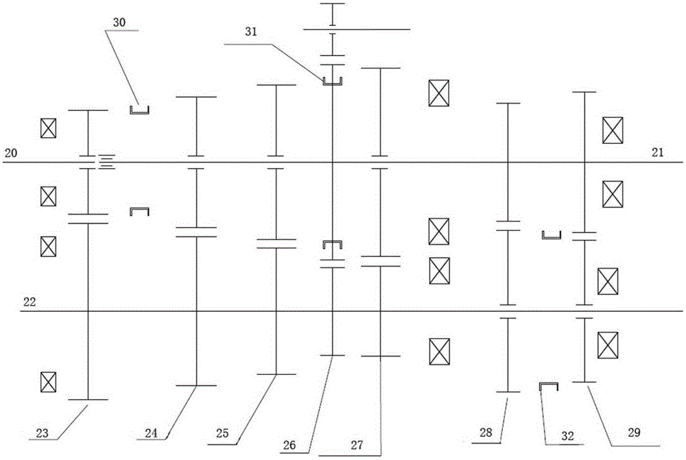
[0041] The transmission gear structure of the second embodiment of the present invention is obtained on the basis of the first embodiment, that is, while keeping the structure of the first embodiment unchanged, only adding a pair of gear transmission pairs can increase two forward gears. , To obtain the transmission gear structure of the second embodiment, specifically,

[0042] Such as figure 2 As shown, in the transmission gear structure of the second embodiment, a seventh gear 7 is relatively rotatably mounted on the output shaft 10, and the seventh gear 7 is assembled in the same manner as the second gear 2, and the second synchronizer 12 can be axially The movement is combined with the second gear 2 or the seventh gear 7 respectively. The eighth gear 8 meshing with the seventh gear 7 is fixedly installed on the intermediate shaft 14 so that two other forward gears can be obtained. figure 2 ,specifically:

[0043] At 5th gear: the first synchronizer 11 is combined with the ...


PUM


Abstract

The invention relates to the field of speed change gears, and provides a speed change gear structure, a transmission and a vehicle. The speed change gear structure comprises an input rotation shaft, an output rotation shaft and a middle rotation shaft; the input rotation shaft is provided with a first gear rotating relatively; the output rotation shaft is provided with a second gear rotating relatively; a third gear is arranged between the input rotation shaft and the output rotation shaft; the middle rotation shaft is provided with a fourth gear meshing with the first gear, a fifth gear meshing with the second gear and a sixth gear meshing with the third gear; the input rotation shaft is provided with a first synchronizer combined with the first gear and the third gear; and the output rotation shaft is provided with a second synchronizer combined with the second gear and a third synchronizer combined with the third gear. Multi-gear output is realized through a few gear transmission pairs, the function of each gear is maximized, the weight of the transmission is lowered, the cost of the transmission is lowered, the size is optimized, and the number of the rotating gears is reduced at idle so that the churning loss of idling can be reduced and abnormal sounds of idling can be lowered.

Description

Technical field [0001] The present invention relates to the technical field of transmission gears, in particular to a transmission gear structure, a transmission with the transmission gear structure, and a vehicle with the transmission. Background technique [0002] More than 95% of the transmissions of existing vehicles are geared to achieve stable and reliable power transmission. In addition, with the development of vehicle technology, the shifting gears of the vehicle are correspondingly increased to meet the shifting needs of users in different gears. [0003] For example, in an existing vertical mechanical 6-speed manual transmission, the input shaft 20 and the output shaft 21 are coaxial, and the intermediate shaft 22 is arranged parallel to the input shaft 20 and the output shaft 21, of which, three A fourth gear pair 23, a third gear pair 24, a second gear pair 25, an R gear pair 26, a first gear pair 27, a sixth gear pair 28, and a fifth gear are sequentially assembled on...

Claims


Application Information

Patent Timeline
IPC IPC(8): F16H3/12F16H3/091F16H57/023
CPCF16H3/12F16H3/0915F16H57/023F16H2003/0803F16H2003/0826
Inventor 史江海乔彦辉王力朋王伟刘建国龚正伟
Owner GREAT WALL MOTOR CO LTD
Why Eureka
Try Eureka