Numerical controller for controlling collision position of cutter tip of tool and workpiece

A numerical control device and cutting tool technology, applied in program control, manufacturing tools, digital control, etc., can solve problems such as inability to eliminate blade chipping, and achieve the effect of suppressing chipping

Inactive Publication Date: 2017-04-05
FANUC LTD
View PDF7 Cites 2 Cited by
  • Summary
  • Abstract
  • Description
  • Claims
  • Application Information

AI Technical Summary

Problems solved by technology

[0006] However, even with these conventional technologies, there are cases where chipping of the insert cannot be eliminated

Method used


Image

  • Numerical controller for controlling collision position of cutter tip of tool and workpiece
  • Numerical controller for controlling collision position of cutter tip of tool and workpiece
  • Numerical controller for controlling collision position of cutter tip of tool and workpiece

Examples


Embodiment Construction

[0033] Embodiments and drawings of the present invention will be described below.

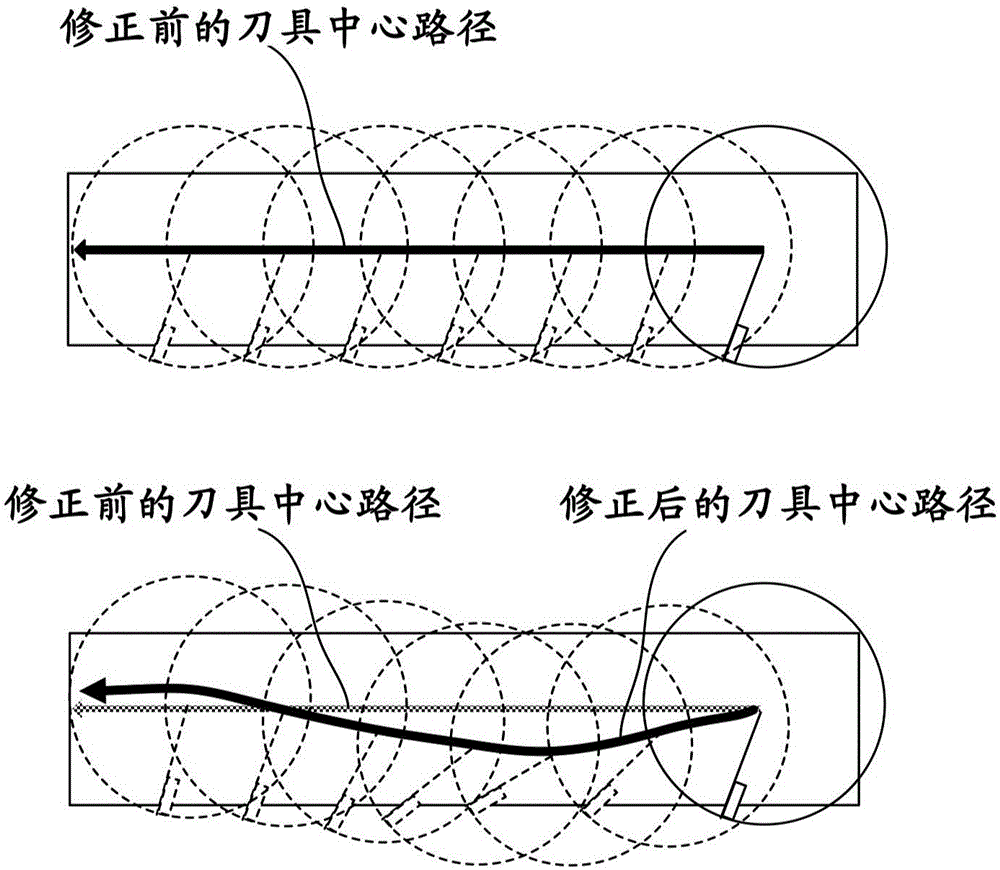
[0034] In the present embodiment, in end mill machining using a tool with inserts, as figure 1 As shown, the tool position is corrected in the vertical direction from the (programmed) tool center path determined by the program, so that the collision position between the blade and the workpiece is not concentrated on a specific position of the blade.

[0035] The present embodiment provides a numerical control device that generates a relationship between the insert and the workpiece based on the information on the tool having the insert used in end mill machining, the shape information of the workpiece, and the information on the use range of the insert. The collision location is not centered on the toolpath at a specific location of the insert.

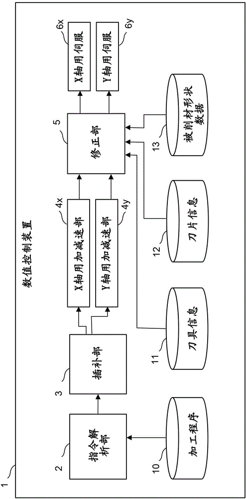
[0036] figure 2 It is a schematic configuration diagram of the numerical controller of this embodiment. The numerical controller 1 of the present...


PUM


Abstract

The invention provides a numerical controller for controlling collision position of cutter tip of tool and workpiece. A tool center path is compensated so that the number of collisions with a workpiece in positions on cutter tips complies with use frequencies in cutter tip information, based on tool information including the diameter of a tool and the number of cutter tips attached to the tool, a tool center movement path specified by a machining program, workpiece shape data, and cutter tip information.

Description

[0001] This application is based on Japanese Patent Application No. 2015-193278 filed on September 30, 2015 in Japan as a priority application. The content of the Japanese application is incorporated in the content of the present application by reference. technical field [0002] The present invention relates to a numerical control device, in particular to a numerical control device for controlling the collision position between a blade of a tool and a workpiece. Background technique [0003] In rough machining of end mills, etc., if the cutting angle (feed angle) of the insert into the workpiece is too large, the chip thickness when the insert cuts into the workpiece becomes thinner, and the workpiece elastically deforms. Therefore, a large force is applied to the tip of the blade, and chipping is likely to occur. On the other hand, when the infeed angle is too small, the chip thickness when the insert cuts into the workpiece becomes thick, and the impact on the insert inc...

Claims


Application Information

Patent Timeline
Patent Type & Authority Applications(China)
IPC IPC(8): G05B19/19
CPCG05B19/19G05B2219/35349G05B19/404B23C3/00G05B2219/35101B23C2220/60G05B19/29G05B2219/49172
Inventor 远藤胜博
Owner FANUC LTD
Why Eureka
Try Eureka