Yagi antenna

A Yagi antenna and metamaterial technology, applied in the field of end-fire antennas, can solve the problem that frequency scanning antenna information cannot be timely fed back and tracked.

Active Publication Date: 2017-04-05
SOUTH UNIVERSITY OF SCIENCE AND TECHNOLOGY OF CHINA
View PDF3 Cites 5 Cited by
  • Summary
  • Abstract
  • Description
  • Claims
  • Application Information

AI Technical Summary

Problems solved by technology

[0003] However, due to the limitation of the radiation direction of the traditional Yagi antenna, the radiation range of the frequency scanning antenna is limited to the range of

Method used


Image

  • Yagi antenna
  • Yagi antenna
  • Yagi antenna

Examples


Example Embodiment

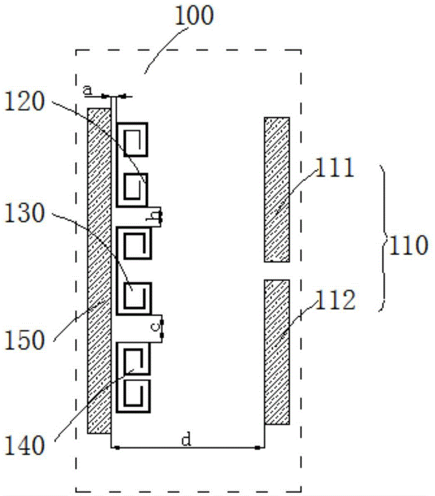
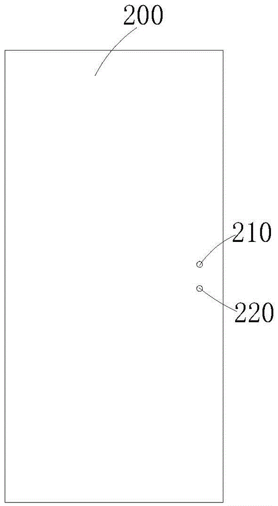
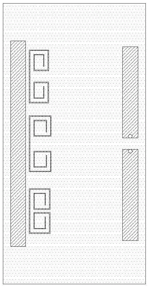
[0025] In order to explain the Yagi antenna provided by the present invention more clearly, a specific description will be given below in conjunction with embodiments. figure 1 It is an appearance structure diagram of the printed metal layer of the Yagi antenna according to an embodiment. figure 2 for figure 1 The appearance structure diagram of the dielectric substrate of the Yagi antenna of the illustrated embodiment. image 3 for figure 1 The overall appearance structure diagram of the Yagi antenna of the illustrated embodiment. Figure 4 for figure 1 The reflection coefficient diagram of the Yagi antenna of the illustrated embodiment. Figure 5 for figure 1 The gain map of the Yagi antenna of the illustrated embodiment in the +Z and -Z directions in the frequency band from 1.6 GHz to 3 GHz, respectively. Figure 6 to Figure 9 for figure 1 The far-field E-plane patterns of the Yagi antenna of the illustrated embodiment are respectively at 2.06 GHz, 2.18 GHz, 2.33 GHz, and 2.46...


PUM

PropertyMeasurementUnit
Total lengthaaaaaaaaaa

Abstract

The invention relates to a Yagi antenna, which comprises a printed metal layer and a dielectric substrate, wherein the printed metal layer is printed on the dielectric substrate; the printed metal layer comprises a dipole unit, a plurality of metamaterial units and a metal strip reflector; the dipole unit and the metal strip reflector enable the Yagi antenna to have a first pattern and enable the Yagi antenna to still keep the traditional radiation feature; the metamaterial units and the metal strip reflector together form a medium with a negative dielectric constant and a negative permeability and enable the Yagi antenna to have another radiation feature, and a second pattern with the radiation direction opposite to the first pattern is provided; and the dipole unit and each metamaterial unit enable the Yagi antenna to have different working bands respectively, and thus, normal working of the Yagi antenna under the above two radiation features can be ensured respectively. Thus, the Yagi antenna has two patterns with the opposite radiation directions under different working bands, and compared with the traditional Yagi antenna, the radiation range is expanded.

Description

technical field [0001] The invention relates to the technical field of end-fired antennas, in particular to a Yagi antenna. Background technique [0002] In the field of end-fired antennas, Yagi antennas are widely used in direction finding, tracking, and long-distance communication systems because of their good directivity and higher gain than dipole antennas. At the same time, with the rapid development of modern communication systems, the performance requirements for antenna patterns are getting higher and higher, and frequency scanning antennas based on Yagi antennas have emerged. The frequency scanning antenna can realize the functions of identification, search, tracking and passive detection through its beam scanning capability. [0003] However, due to the limitation of the radiation direction of the traditional Yagi antenna, the radiation range of the frequency scanning antenna is limited to the range of ±90 degrees from the maximum radiation direction, and the info...

Claims


Application Information

Patent Timeline
IPC IPC(8): H01Q19/30H01Q1/38H01Q1/36
Inventor 王伟王锐陈万里王海朱晓丹李风从
Owner SOUTH UNIVERSITY OF SCIENCE AND TECHNOLOGY OF CHINA
Why Eureka
Try Eureka