
An angle-adjustable solar panel mounting bracket

A technology for solar panels and mounting brackets, applied in solar thermal power generation, fixed bases/supports of solar collectors, solar thermal energy, etc., to achieve the effect of simple structure and improved energy utilization

Active Publication Date: 2018-08-24
广州市友乃德金属制品有限公司
View PDF6 Cites 0 Cited by
  • Summary
  • Abstract
  • Description
  • Claims
  • Application Information

AI Technical Summary

Problems solved by technology

Existing existing solar cells are generally installed obliquely on the mounting bracket in order to absorb sunlight well. Generally, the bracket can only be adjusted up and down, which has limitations, so a mounting bracket that can be adjusted at all angles is required to serve the solar panel

Method used


Image

  • An angle-adjustable solar panel mounting bracket
  • An angle-adjustable solar panel mounting bracket
  • An angle-adjustable solar panel mounting bracket

Examples


Embodiment Construction

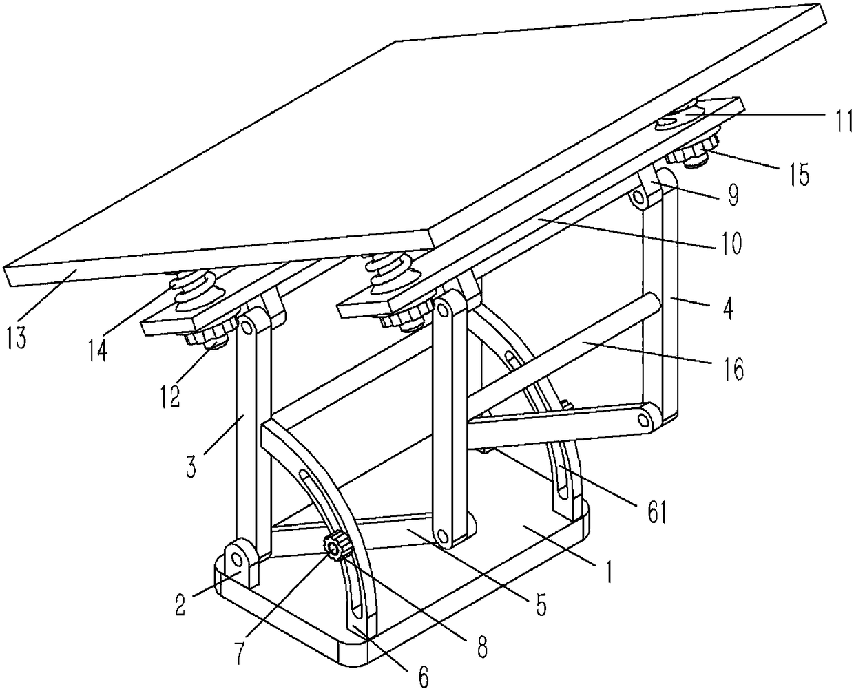
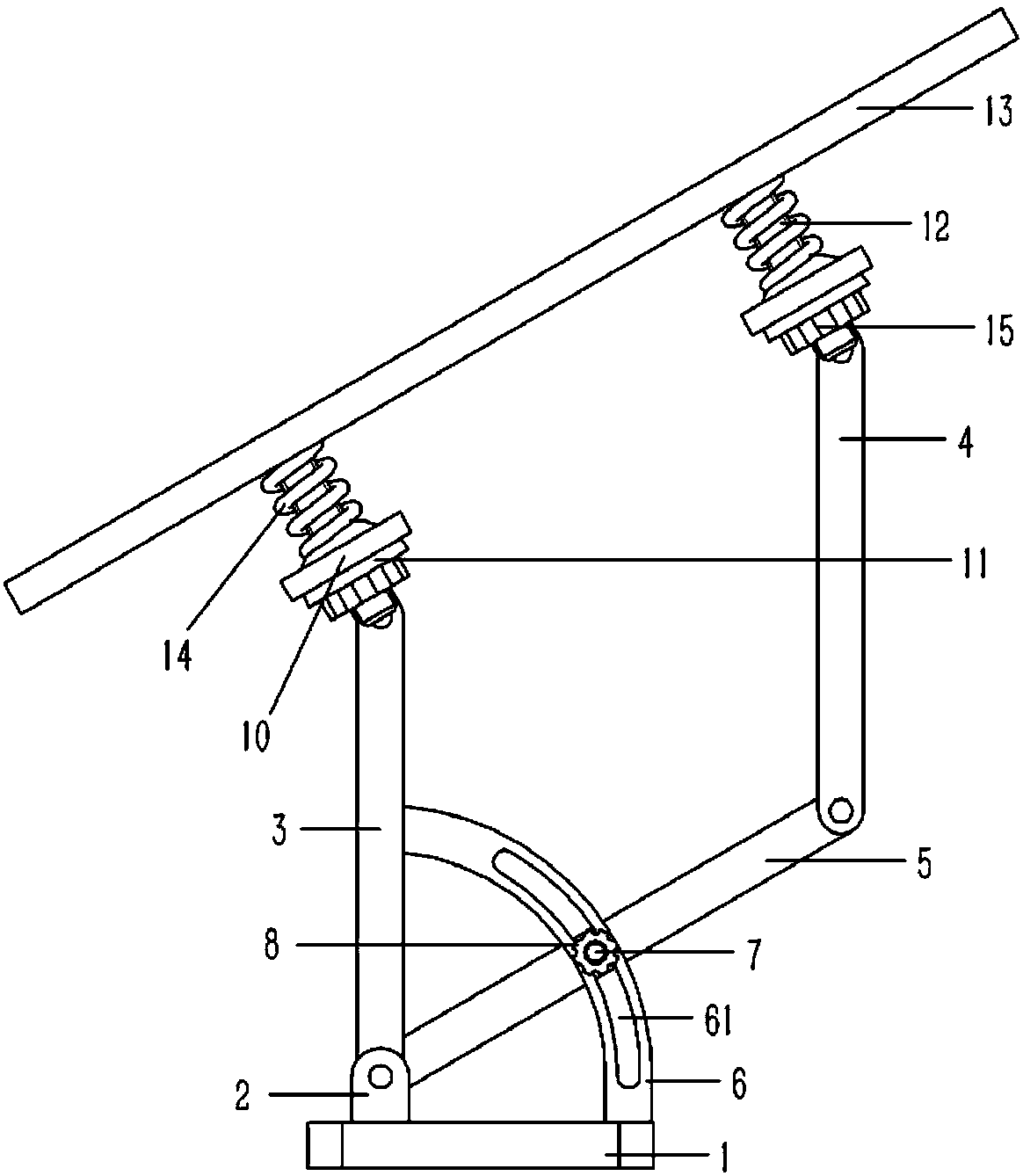
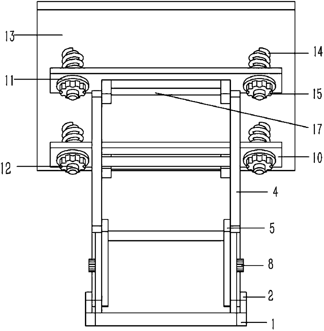
[0016] Example: see Figures 1 to 3 As shown, an angle-adjustable solar panel mounting bracket includes a fixed bottom plate 1, and the two ends of the front side of the fixed bottom plate 1 are fixed with a first hinge seat 2, and a vertical front support is hinged on the first hinge seat 2 Rod 3, the rear side of the front support rod 3 is provided with a vertical rear support rod 4, the two ends of the connecting rod 5 are respectively hinged with the lower ends of the front support rod 3 and the rear support rod 4 through the hinge shaft, and the connecting rod 5 is against the The arc-shaped adjustment rod 6, the lower end of the adjustment rod 6 is fixed on the fixed base plate 1, the upper end of the adjustment rod 6 is fixed on the front support rod 3, and an arc-shaped guide groove 61 is formed on the adjustment rod 6, the guide groove 61 A stud 7 is inserted inside, one end of the stud 7 is fixed on the connecting rod 5, and the other end of the stud 7 passes through...


PUM


Abstract

The invention discloses a solar cell panel installation support with adjustable angle. The support comprises a fixed base plate. The two ends at the front side of the fixed base plate are fixedly provided with a first articulation base each. The first articulation base is articulated to a vertical front support rod. The back side of the front support rod is provided with a vertical back support rod. The two ends of a connection rod are articulated to the front support rod and the lower end of the back support rod respectively through articulation shafts. The connection rod abuts against an arc adjusting rod. The lower end of the adjusting rod is fixedly arranged on the fixed base plate while the upper end is fixedly arranged on the front support rod. The adjusting rod is provided with an arc shaped direction guiding groove. The direction guiding groove is inserted by a screw post. One end of the screw post is fixed on the connection rod while the other end penetrates the adjusting rod and is connected with the first adjusting nuts through screws. Simple in structure, the support can be adjusted in full angles so as to meet the solar cell panel's requirement to receive sunlight and to increase the energy utilization efficiency of solar cell panel.

Description

Technical field: [0001] The invention relates to the technical field of solar battery panels, and more specifically relates to an angle-adjustable solar battery panel mounting bracket. Background technique: [0002] As we all know, a solar panel is a device that directly or indirectly converts solar radiation into electrical energy through photoelectric or chemical effects by absorbing sunlight. Existing existing solar cells are generally installed obliquely on the mounting bracket in order to absorb sunlight well. Generally, the bracket can only be adjusted up and down, which has limitations. Therefore, a mounting bracket capable of full angle adjustment is required to serve the solar panel. Invention content: [0003] The purpose of the present invention is to provide an angle-adjustable solar cell panel mounting bracket for the deficiencies of the prior art, which can realize full-angle adjustment, so as to meet the requirement of the solar cell panel facing sunlight. ...

Claims


Application Information

Patent Timeline
Patent Type & Authority Patents(China)
IPC IPC(8): H02S20/30F24S30/455
CPCF24S25/10F24S25/70H02S20/30Y02E10/47Y02E10/50
Inventor 赵鸿斌
Owner 广州市友乃德金属制品有限公司
Learn More