Feeding monitoring system and method for material tape of 3D printer

A 3D printer and monitoring system technology, applied in the direction of liquid material additive processing, processing and manufacturing, manufacturing auxiliary devices, etc., can solve problems that affect printing accuracy, poor discharge of printer nozzles, and product defects, etc., to ensure accuracy Effect

Inactive Publication Date: 2017-04-19
DONGGUAN RUIDI THREE DIMENSIONAL ELECTRONICS TECH
View PDF5 Cites 4 Cited by
  • Summary
  • Abstract
  • Description
  • Claims
  • Application Information

AI Technical Summary

Problems solved by technology

[0009] From the above, we can see that during the printing process, if the material tape cannot be monitored, when the material tape is used up, and the material tape cannot be replenished in time, it will cause the printer nozzle to not discharge smoothly, which will affect the printing accuracy.
Causes flaws in the final printed product

Method used


Image

  • Feeding monitoring system and method for material tape of 3D printer
  • Feeding monitoring system and method for material tape of 3D printer
  • Feeding monitoring system and method for material tape of 3D printer

Examples


Embodiment 1

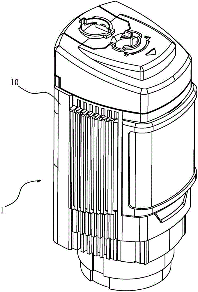
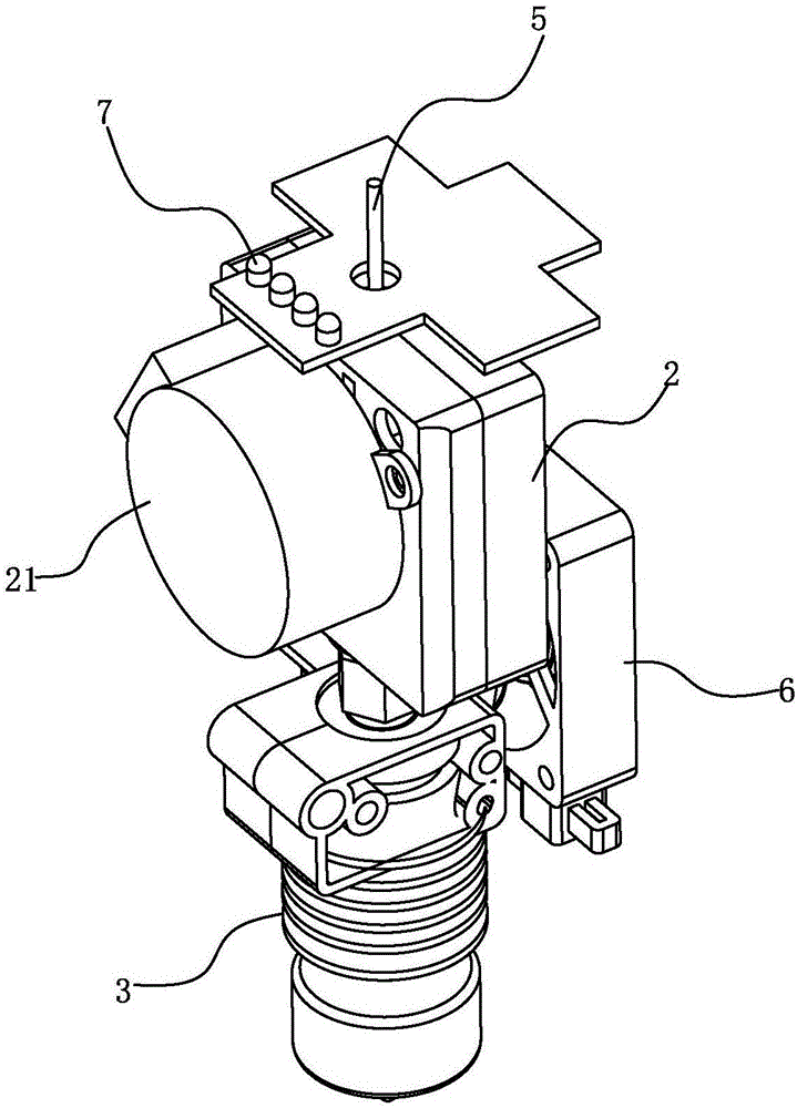
[0036] The solution adopted in Embodiment 1 of the present invention is to integrate the monitoring system inside the print head 1 . See Figure 2-Figure 5 As shown, the print head 1 has a housing 10 , and a feeding mechanism 2 and a heating unit 3 are installed in the housing 10 from top to bottom, and the feeding mechanism 2 and the heating unit 3 are connected by a feeding tube 30 . The material tape 5 enters the feeding mechanism 2 from the entrance of the upper end of the housing 10 of the print head 1, and the material tape 5 is pushed downward through the feeding mechanism 2. It is heated to become a molten state. When the subsequent strip 5 continues to enter the heating unit 3, it will squeeze the raw material in the heating unit 3, so that the molten raw material is extruded from the nozzle 31 below the heating unit 3.

[0037] The monitoring system in the present embodiment 1 includes a sensor 4, and the sensor 4 is arranged above the feeding end of the feeding mec...

Embodiment 2

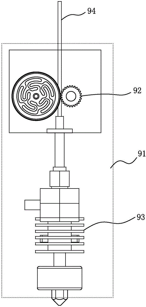
[0049] See Figure 7 It is a structural schematic diagram of Embodiment 2 of the present invention. The difference between the second embodiment and the first embodiment is that in the second embodiment, the feeding mechanism 2 includes two sets of feeding wheels, and the driving wheels 24 of the two sets of feeding wheels are simultaneously linked with the motor 21 . Meanwhile, the sensor 4 in the second embodiment is arranged below the discharge end of the feeding mechanism 2 and above the heating unit 3 .

[0050] In order to ensure the accuracy of feeding and prevent errors in the feeding mechanism, the second embodiment is provided with two sets of feeding wheels, which also include a driving wheel 24 and a driven wheel 25 driven by a motor 21 . The difference from the first embodiment is that in the second embodiment, the two driving wheels 24 both use gears, while the driven wheel 25 uses a friction wheel with a trough. The two driving wheels 24 adopt duplex gears, an...

Embodiment 3

[0054] The third embodiment differs from the first and second embodiments in that: in the third embodiment, the heating unit 3 is arranged inside the print head 1 of the printer, and the feeding mechanism 2 is located outside the print head 1 . According to the first and second embodiments, the sensor 4 can be set in the print head 1 or in the feeding mechanism 2 . Certainly the best way is to be arranged in the feeding mechanism 2, so that when the material tape 5 is used up, the sensor 4 can monitor this situation in time. When the sensor 4 is arranged in the feeding mechanism 2, the sensor 4 can be arranged above the feeding end of the feeding mechanism 2, and can also be arranged below the discharging end of the feeding mechanism. If feeding mechanism 2 adopts multiple sets of feed wheel sets, it can also be arranged between the gift-giving wheel sets.

[0055] In summary, the feeding monitoring method of the material tape adopted in the present invention is to monitor th...


PUM


Abstract

The invention discloses a feeding monitoring system and method for a material tape of a 3D printer. The feeding monitoring system for the material tape of the 3D printer comprises a conveying mechanism and a heating unit, and the material tape enters a heating unit under driving of the conveying mechanism. The monitoring system further comprises a sensor, and the sensor is arranged above the feeding end of the conveying mechanism or arranged between the conveying mechanism and the heating unit, the sensor acts on the material tape in a pressing triggering or optical triggering mode, and the sensor is triggered when the material tape is used up. According to the feeding monitoring system and method for the material tape of the 3D printer, the sensor is arranged for monitoring the material tape, so that problems which possibly occur when the material tape is used up are solved, it is guaranteed that discharging for printing of the printer is not affected when a new material tape is arranged, and the printing precision is ensured.

Description

[0001] Technical field: [0002] The invention relates to the technical field of 3D printer products, in particular to a feed monitoring system and method for a 3D printer tape. The present invention realizes real-time monitoring of the 3D printer tape. When the tape is exhausted, the printer stops printing. until the tape is reloaded. [0003] Background technique: [0004] 3D printers have developed rapidly in the past few years. The existing 3D printers first need to use a computer to model before working, and then perform layered "slicing" of the built 3D model, and then "print" layer by layer from bottom to top. ” Each layer is sliced, resulting in a 3D product identical to the model built. [0005] This kind of 3D printer is also called hot-melt material spray printing. Its working principle is similar to that of traditional inkjet printers. The difference is that the "ink" used by this 3D printer is a kind of hot-melt material, such as hot-melt wax , Hot melt adhesive....

Claims


Application Information

Patent Timeline
Patent Type & Authority Applications(China)
IPC IPC(8): B29C64/393B29C64/106B33Y50/02
CPCB33Y50/02
Inventor 赵舜培赵俊明
Owner DONGGUAN RUIDI THREE DIMENSIONAL ELECTRONICS TECH
Why Eureka
Try Eureka