Control method and control device for groundwater in deep foundation pit

A control method and technology for groundwater, applied in infrastructure engineering, construction, etc., can solve the problems of heavy workload, poor precipitation effect, and high investment cost, and achieve the effect of improving strength and good precipitation effect.

Active Publication Date: 2018-10-02
CHINA MCC20 GRP CORP +1
View PDF5 Cites 0 Cited by
  • Summary
  • Abstract
  • Description
  • Claims
  • Application Information

AI Technical Summary

Problems solved by technology

[0003] One of the purposes of the present invention is to provide a method for controlling groundwater in deep foundation pits to solve the problem of large workload in the prior art when pouring foundation pit floors in deep foundation pits
[0004] The second purpose of the present invention is to provide a deep foundation pit groundwater control device to solve the problems of poor dewatering effect and high investment cost in the existing deep foundation pit groundwater control device

Method used


Image

  • Control method and control device for groundwater in deep foundation pit
  • Control method and control device for groundwater in deep foundation pit

Examples


Embodiment 1

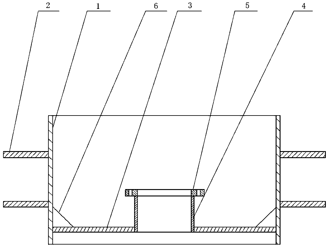
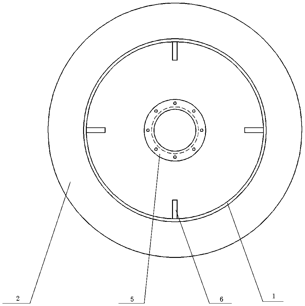
[0026] Such as figure 1 with figure 2 As shown, the method for controlling groundwater in a deep foundation pit of the present invention includes the following steps:

[0027] a. According to the geological survey report and on-site field experience, select the confluence of the groundwater system at the bottom of the foundation pit, and start digging the water collection pit at the position corresponding to the confluence of the groundwater system in the vertical direction at the bottom of the foundation pit. The depth is 1000 mm ~ 1200 mm. There are multiple drainage ditches connected to the sump at the bottom of the foundation pit. The width of the drainage ditches is 300 mm, and the depth of the drainage ditches is 100 mm. Lay the bottom half of the drainage ditches. There are stones with a particle diameter of 10 mm to 30 mm, and stones with a particle diameter of 5 mm to 10 mm are laid on the upper part of the drainage ditch, that is, stones with a particle diameter of 10 ...

Embodiment 2

[0035] Such as figure 1 with figure 2 As shown, the device for controlling groundwater of a deep foundation pit of the present invention includes an outer sleeve 1 and a lower dewatering well pipe 4 arranged in the outer sleeve 1. The outer sleeve 1 is a spiral welded pipe. The height of the outer sleeve 1 is slightly smaller than the sum of the thickness of the bottom layer to be poured and the thickness of the bottom of the foundation pit to be poured. The outer diameter of the outer sleeve 1 is 900 mm ~ 1000 mm, and the outer sleeve The inner diameter of the cylinder 1 is 50-100 mm larger than the inner diameter of the sump, and the wall thickness of the outer sleeve 1 is 10 mm. An annular outer water stop ring 2 is welded to the upper and lower parts of the outer wall surface of the outer sleeve 1, and the width of the outer water stop ring 2 is greater than or equal to 200 mm. The outer water stop ring 2 at the upper part of the outer sleeve 1 is arranged at the upper 1 / ...


PUM


Abstract

The invention provides a method and a device for controlling underground water of a deep foundation pit. The method comprises the following steps: digging a water collecting pit in a place where underground water systems gather; taking a section of a spiral welded pipe as an outer sleeve, wherein an outer water-stop ring is welded to the outer wall surface of the outer sleeve and an inner water-stop ring is welded onto the inner wall surface of the outer sleeve; taking a section of a steel pipe as a dewatering well pipe, wherein the dewatering well pipe is arranged at the inner lower part of the outer sleeve and a connecting flange is welded to the top end of the dewatering well pipe; putting a submersible pump into the water collecting pit for water pumping operation; after the pouring of a baseplate cushion layer is finished, starting to bind a steel reinforcement cage required for the pouring of a baseplate of the foundation pit; and performing concrete pouring on the baseplate of the foundation pit, shutting down and taking out the submersible pump after the design requirements are met, and mounting a blind flange on the connecting flange. By adoption of the method and the device provided by the invention, the problem that when a supporting-type deep foundation pit without a slope is dug, concrete pouring cannot be performed on the baseplate of the foundation pit because an underground river or rock crevice water is cut off can be solved; and a good dewatering effect is exerted on the practical engineering application.

Description

Technical field [0001] The invention relates to a drainage technology for foundation pit engineering, in particular to a method and device for controlling groundwater in a deep foundation pit. Background technique [0002] The production and operation of most modern industries are inseparable from the consumption of a large amount of water, so the site selection is closer to the water source, such as close to rivers, lakes and coastal areas. The underground geological structure of these areas is more variable and the groundwater system is more complicated. When part of the structure in the industrial structure is limited by the excavation surface, when the excavation of the supporting deep foundation pit without grading is carried out, the excavation of the foundation pit reduces the thickness of the impervious layer over the aquifer to a certain extent Later, you will inevitably encounter confined water in the groundwater, where the head pressure of the confined water can top up...

Claims


Application Information

Patent Timeline
Patent Type & Authority Patents(China)
IPC IPC(8): E02D19/00E02D19/10E02D19/20E02D19/22
CPCE02D19/00E02D19/10E02D19/20E02D19/22
Inventor 马勇郎海洋李庆刚
Owner CHINA MCC20 GRP CORP
Why Eureka
Try Eureka