
Holder calibration method

A calibration method and the technology of the cloud platform, applied in the field of the cloud platform, can solve the problems of inconvenient operation and tool requirements, complicated calibration process, tilted shooting screen, etc.

Inactive Publication Date: 2017-04-19
JIYI ROBOT SHANGHAI
View PDF14 Cites 28 Cited by
  • Summary
  • Abstract
  • Description
  • Claims
  • Application Information

AI Technical Summary

Problems solved by technology

In order to determine the relative position relationship between the angle sensor component and the gimbal at the factory, mechanical calibration is required, and the mechanical calibration generally requires the use of fixtures at this stage. Put the gimbal into the calibration jig to keep the gimbal at the mechanical zero position, and connect the gimbal Calibrate through the calibration software after powering on. This method will bring additional operations and tool requirements due to the need for fixtures, which is extremely inconvenient.
[0004] The IMU components composed of MEMS sensors are widely used on the gimbal because of their lightness and high integration. However, factors such as installation errors and easy to be affected by the ambient temperature will cause the actual angle of the bearing equipment on the gimbal to be different from that measured by the IMU components. The results do not match, causing the shot to be skewed, so it needs to be adjusted by calibration
At present, the commonly used calibration method is to perform multi-position calibration on the gimbal system, such as the six-sided calibration method, but the calibration process of this method is complicated and takes a long time

Method used


Image

  • Holder calibration method
  • Holder calibration method
  • Holder calibration method

Examples


Embodiment Construction

[0024] The present invention will be further described below in conjunction with the accompanying drawings and specific embodiments, but it is not intended to limit the present invention.

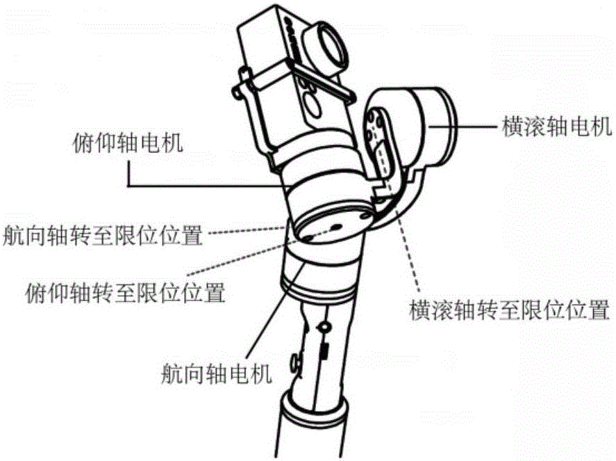
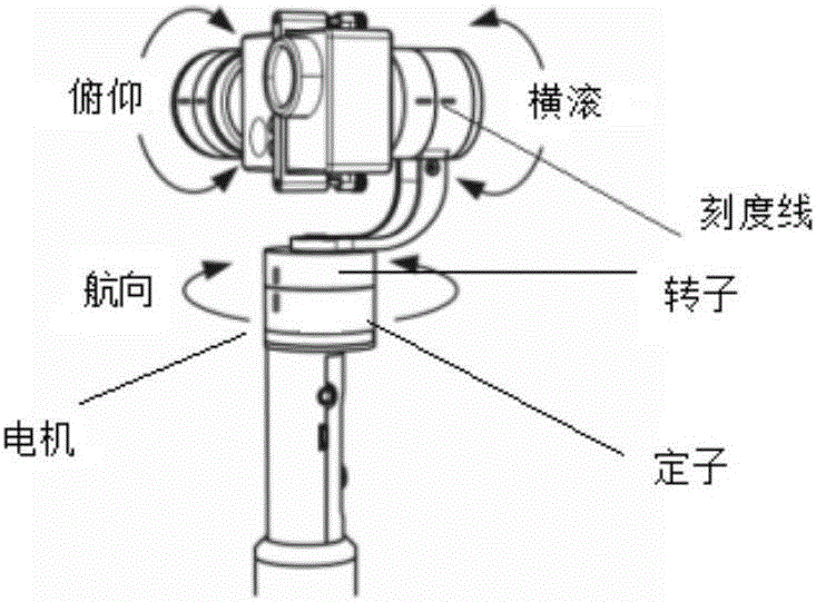
[0025] The pan / tilt system includes bearing equipment, induction components, drive motors and their connecting shafts, micro control units (MCUs) and their control components and other components. The carrying equipment is generally a camera or mobile phone and other shooting devices; the sensing component mainly includes an angle sensor and an inertial measurement component, which are set on the motor component and connected with the motor for real-time monitoring of the movement status of the carrying equipment; the driving motor of the three-axis gimbal Its connecting shafts are generally composed of 3 groups, one of which is the pitch axis and the pitch axis motor, which is used to drive the bearing equipment to rotate along the pitch axis, and the other group is the roll axis and roll a...


PUM


Abstract

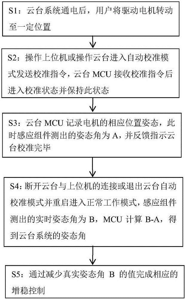
The invention discloses a holder calibration method. The method comprises the steps that a holder driving motor is rotated to a motor limit gear or a position where a marked graduation line of the motor is located or a position when a mobile phone is horizontal after a holder is electrified; a user operation host computer sends a calibration instruction, and a holder MCU receives the calibration instruction, enters a calibration state and records a corresponding position attitude A of the motor; and the holder is disconnected from the host computer and restarted to enter a normal work mode, an IMU assembly measures a real-time attitude angel B, and the MCU obtains the real attitude angle of the holder by calculating B-A. The holder calibration method is characterized by simple operation, high calibration efficiency and high reliability.

Description

technical field [0001] The invention relates to the field of cloud platforms, in particular to a method for calibrating a cloud platform. Background technique [0002] The gimbal is a load-bearing device for installing and fixing cameras or mobile phones and other shooting devices. It can monitor external disturbances according to the attitude sensing component, drive the motor to rotate the connected structural components, and keep the camera or mobile phone at a stable level, thereby ensuring the quality of the shooting picture. [0003] The gimbal attitude sensing component is generally composed of an angle sensor component and an inertial measurement unit (IMU). They are fixedly connected to the motor and can monitor the motion status of the camera or mobile phone in real time, especially the horizontal attitude angle. In order to determine the relative position relationship between the angle sensor component and the gimbal at the factory, mechanical calibration is requi...

Claims


Application Information

Patent Timeline
IPC IPC(8): G05D3/12
CPCG05D3/12
Inventor 王祥凡吴孟李亚
Owner JIYI ROBOT SHANGHAI
Learn More