
Glass plate and method for manufacturing same

A manufacturing method and technology for glass plates, applied in the input/output process of instruments, coatings, data processing, etc., can solve problems such as scratches on the lower surface of the glass ribbon, and achieve the effect of inhibiting the generation of white turbidity

Inactive Publication Date: 2017-04-19
ASAHI GLASS CO LTD
View PDF5 Cites 3 Cited by
  • Summary
  • Abstract
  • Description
  • Claims
  • Application Information

AI Technical Summary

Problems solved by technology

At this time, the lower surface of the glass ribbon may be scratched by the transport tool

Method used


Image

  • Glass plate and method for manufacturing same
  • Glass plate and method for manufacturing same
  • Glass plate and method for manufacturing same

Examples


Embodiment

[0092] Hereinafter, examples of the present invention will be specifically described, but the present invention is not limited to these.

[0093] In this example, a glass plate of a glass material having the following composition was used.

[0094] In mol%, it contains 64.2% SiO 2 , 8.0% Al 2 O 3 , 12.5% ​​Na 2 O, 4.0% K 2 O, 10.5% MgO, 0.1% CaO, 0.1% SrO, 0.1% BaO, 0.5% ZrO 2 Glass plate

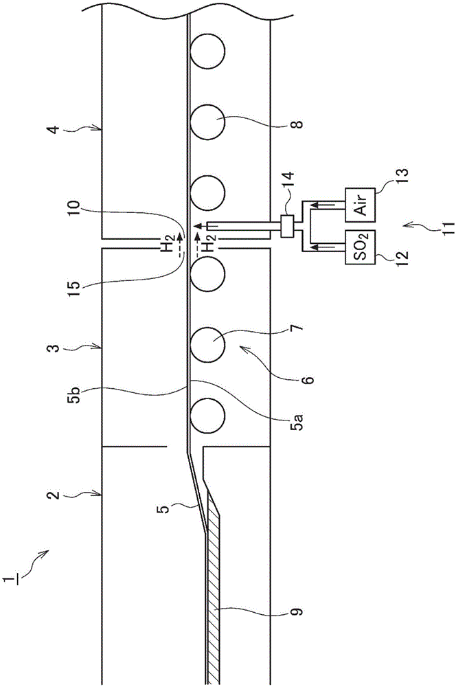
[0095] With the buffer layer forming device 11, the SO2 was removed at the upstream end of the annealing furnace 4 at the supply amount shown in Table 2. 2 And air is supplied to the bottom surface 5a of the glass ribbon 5.

[0096] [Table 2]

[0097]

[0098] It should be noted that although in figure 1 Although not shown in the figure, in the annealing furnace 4 of the present embodiment and the comparative example, five other buffer layer forming devices (downstream buffer layer forming devices) are provided on the downstream side of the buffer layer forming device 11. The five downstream buffer ...


PUM

PropertyMeasurementUnit
diameteraaaaaaaaaa
surface roughnessaaaaaaaaaa

Abstract

This glass plate has on the bottom surface thereof a buffer layer formed of a plurality of sulfate crystals, such bottom surface making contact with molten metal when carrying out formation by the float method. The median value of the circle equivalent diameters of the plurality of sulfate crystals, as seen from the thickness direction, is 350nm or less.

Description

Technical field [0001] The invention relates to a glass plate and a manufacturing method thereof. Background technique [0002] In recent years, in flat-panel display devices such as mobile phones, smart phones, tablet terminals, personal computers, televisions, car navigation display devices, etc., in order to improve the protection and aesthetics of the displays, the following operations have been carried out: The front of the display acts as a protective glass to form a wider area than the image display part. [0003] Such an existing glass plate can be manufactured using a method called float method, for example. When using the float method to manufacture glass plates, use a melting furnace that melts the raw materials of glass, a float float furnace that floats molten glass on molten metal (tin, etc.) to form a glass ribbon, and an annealing furnace that anneals the glass ribbon Glass manufacturing equipment. [0004] Here, when the glass ribbon is conveyed from the float fur...

Claims


Application Information

Patent Timeline
Patent Type & Authority Applications(China)
IPC IPC(8): C03C17/22C03B18/02C03C15/00G06F3/041
CPCC03C15/00C03C17/22G06F3/041C03C3/087C03C17/002C03C17/007C03C2217/42C03C2217/47C03C2218/33C03C2218/355C03C2218/36C03B18/02C03C15/02
Inventor 世良洋一秋山良司川上干通谷井史朗中野胜之秋江大树岸川知子
Owner ASAHI GLASS CO LTD
Learn More