Supercharge Your Innovation With Domain-Expert AI Agents!

Device for clamping multiple workpieces

A clamping device and multi-workpiece technology, applied in positioning devices, metal processing machinery parts, clamping, etc., can solve problems such as insufficient clamping force, complete suspension, tool breakage, etc., to ensure clamping stability and guarantee The effect of stability

Active Publication Date: 2017-04-26
ZHUHAI FENGGU ELECTRONICS TECH CO LTD
View PDF7 Cites 6 Cited by
  • Summary
  • Abstract
  • Description
  • Claims
  • Application Information

AI Technical Summary

Problems solved by technology

However, since the adsorption force is directly proportional to the adsorption area, when the part is too small and the effective adsorption area is insufficient, the part is easy to loosen during processing, resulting in tool breakage, unstable processing size, poor surface quality and many other problems. Therefore, the vacuum adsorption method is not suitable for the processing and fixing of small-sized parts.
[0003] Due to its mechanical structure, the traditional vise can provide stable and reliable mechanical clamping force for parts clamping. However, due to structural limitations, there will be a certain fit gap between the movable jaw of the vise and the slide rail. When the movable jaw Under the condition of clamping force, the jaw will produce a small amount of inclination. At this time, if multiple parts of the same type are clamped at one time, usually only 2 to 3 parts can be effectively clamped, and the remaining parts will have clamping force. Insufficient or even completely suspended. In actual processing, in order to ensure reliable clamping, generally only 1 to 2 parts are clamped at a time, which seriously restricts the improvement of processing efficiency and cannot be applied to the processing of large-scale products.

Method used


Image

  • Device for clamping multiple workpieces
  • Device for clamping multiple workpieces
  • Device for clamping multiple workpieces

Examples


Embodiment 1

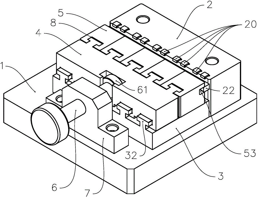
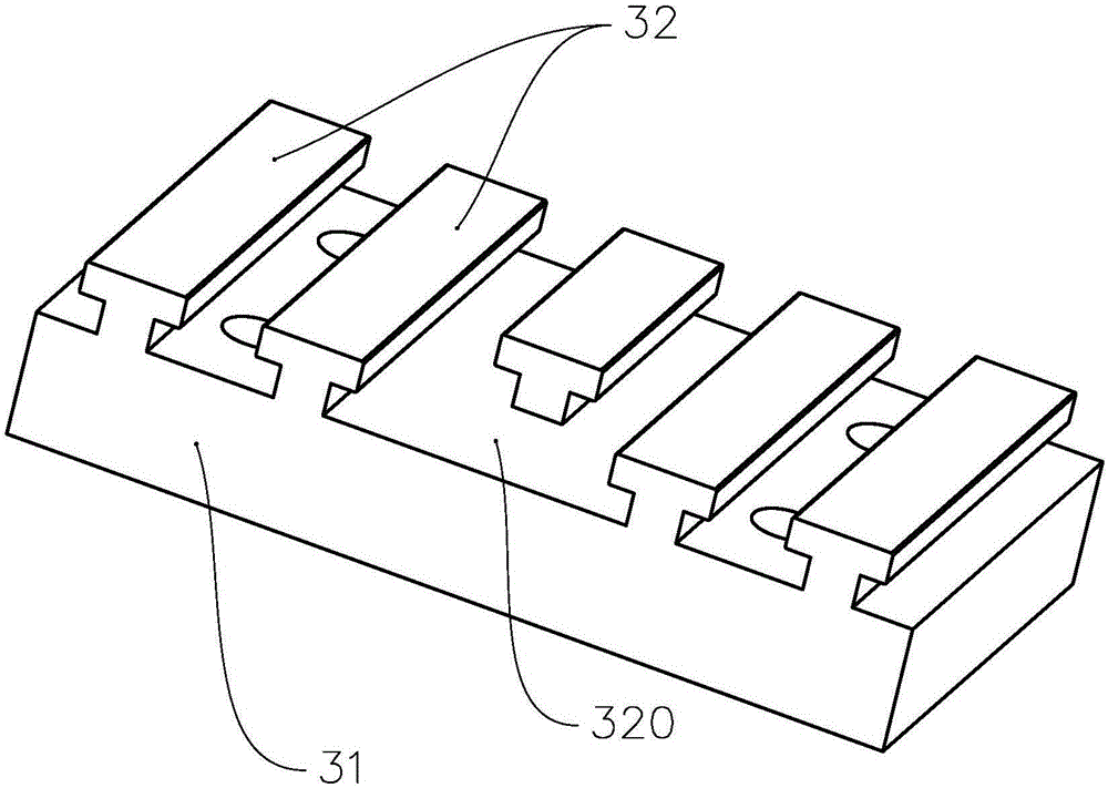
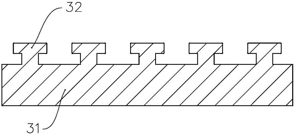
[0036] see figure 1 , figure 1 It is a structural diagram of Embodiment 1 of the multiple workpiece clamping device of the invention. The multi-workpiece clamping device includes a base plate 1, a fixing seat 2 and a clamping device, and the clamping device includes a slide rail 3, a first slider 4, a second slider 5, a screw 6 and a bracket 7, and the fixing seat 2 and the clamping device Set on base plate 1. The slide rail 3 is arranged between the fixed seat 2 and the bracket 7, the first slide block 4 and the second slide block 5 are slidably arranged on the slide rail 3, the first slide block 4 is connected with a plurality of second slide blocks 5, The second slider 5 is located between the first slider 4 and the fixing base 2 . Screw rod 6 is provided with external thread, and erected on the support 7, is provided with screw hole on the support 7, is provided with internal thread in the screw hole, and screw rod 6 is threadedly matched with support 7, and one end of ...

Embodiment 2

[0045] see Figure 15 , Figure 15 It is a structural diagram of Embodiment 2 of the multiple workpiece clamping device of the present invention. In this embodiment, the multiple workpiece clamping station includes a bottom plate 100 , a fixing seat 200 , a clamping assembly 300 , a clamping assembly 400 , a clamping assembly 500 and a clamping assembly 600 . The structures of the clamping assembly 300 , the clamping assembly 400 , the clamping assembly 500 and the clamping assembly 600 are the same as those of the clamping assembly in Embodiment 1, and will not be repeated here. The clamping assembly 400 , the clamping assembly 500 and the clamping assembly 600 are arranged symmetrically on both sides of the fixing base 200 . A plurality of workpiece clamping positions and receiving blocks are arranged symmetrically on the fixed seat 200 .

[0046] The advantage of using the multi-workpiece clamping device of the present invention is: turning the screw rod drives the first...


PUM


Abstract

The invention provides a device for clamping multiple workpieces. The device for clamping the multiple workpieces comprises a base plate, a fixing seat and clamping assemblies. The fixing seat and the clamping assemblies are arranged on the base plate; each clamping assembly comprises a slide rail, a first slide block, second slide blocks, a screw rod and a support; the fixing seat, the slide rails and the supports are fixed onto the base plate; each slide rail is arranged between the fixing seat and the corresponding support; each first slide block and the second slide blocks can be slidably arranged on each slide rail; each first slide block is connected with a plurality of second slide blocks; the second slide blocks are located between the first slide block and the fixing seat; a plurality of workpiece clamping stations are arranged on junction parts of a top wall and side walls of the fixing seat, and directly face the second slide blocks; each screw rod is erected on the corresponding support and is meshed with the corresponding support; and one end of each screw rod is connected with the corresponding first slide block. The device for clamping the multiple workpieces provided by the invention can be used for simultaneously clamping the processing workpieces stably on a large scale.

Description

technical field [0001] The invention relates to the field of machining, in particular to a clamping device for machining. Background technique [0002] In the field of mechanical processing, how to achieve fast and stable clamping of ultra-small parts that need to be processed in batches has always been an industry problem. The traditional vacuum fixture can clamp multiple workpieces at one time through vacuum adsorption, and the processing efficiency is high. However, since the adsorption force is directly proportional to the adsorption area, when the part is too small and the effective adsorption area is insufficient, the part is easy to loosen during processing, resulting in tool breakage, unstable processing size, poor surface quality and many other problems. Therefore, the vacuum adsorption method is not suitable for processing and fixing small-sized parts. [0003] Due to its mechanical structure, the traditional vise can provide stable and reliable mechanical clampi...

Claims


Application Information

Patent Timeline
IPC IPC(8): B23Q3/06
CPCB23Q3/061
Inventor 杨亦斌
Owner ZHUHAI FENGGU ELECTRONICS TECH CO LTD
Features
  • R&D
  • Intellectual Property
  • Life Sciences
  • Materials
  • Tech Scout
  • Unparalleled Data Quality
  • Higher Quality Content
  • 60% Fewer Hallucinations
Learn More