Heating plate cable protecting device

A protection device and heating plate technology, applied in packaging, transportation, packaging, closing, etc., can solve problems affecting normal use, cable breakage, and affecting heating effects, etc., and achieve the effect of simple operation, reasonable design, and simple structure

Inactive Publication Date: 2017-04-26
PIOTECH CO LTD
View PDF0 Cites 0 Cited by
  • Summary
  • Abstract
  • Description
  • Claims
  • Application Information

AI Technical Summary

Problems solved by technology

[0002] During the transportation, assembly, maintenance and processing of most existing heating plates, due to various reasons, the cables (including resistance wires and thermocouple wires) of the heating plate will be damaged to a certain extent, resulting in the failure of the heating plate. Reduced lifespan and affects its heating effect
[0003] During transportation, due to the inattention of the transportation personnel or the bumps on the road, the cable of the heating plate is often damaged or broken, which affects its normal use.
Secondly, in the process of assembly or processing, since the cables will be exposed outside, the cables of the heating plate may be damaged if the operators or other related personnel do not pay attention.
Another point is that when the heating plate is not used for a long time, the cable of the heating plate will be exposed to the air, and the long-term exposure will affect the insulation effect of the cable, causing the cable to not be used normally.

Method used


Image

  • Heating plate cable protecting device
  • Heating plate cable protecting device
  • Heating plate cable protecting device

Examples


Embodiment

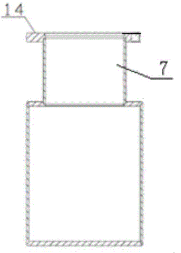
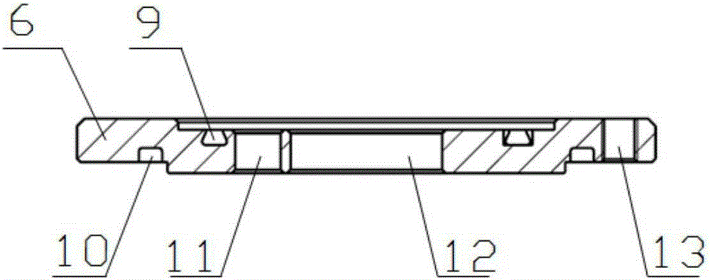
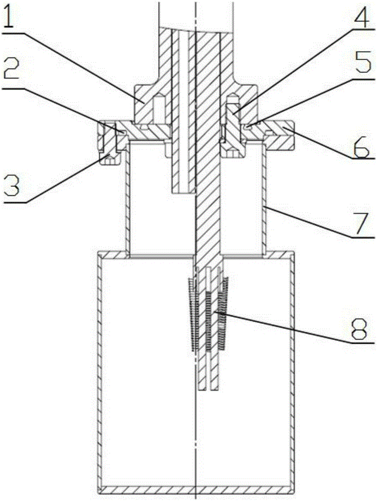
[0016] refer to Figure 1-3 , the heating plate cable protection device, including the cable protection sleeve 7. A sealing ring 2 between the connecting piece and the protective sleeve and a sealing ring 5 between the connecting piece and the fixed end of the heating plate are provided between the cable protection sleeve 7 and the connecting piece 6 and are connected by screws or bolts. First install the sealing ring 5 between the connecting piece and the fixed end of the heating plate and the sealing ring 2 between the connecting piece and the protective sleeve into the sealing groove A9 and sealing groove B10 of the connecting piece 6 respectively, and then install the heating wire of the heating plate 1 8 Pass through the central hole 12 of the connecting piece 6, fix the connecting piece 6 and the fixed end of the heating plate 1 together with the fixing bolt 4 between the connecting piece and the fixed end of the heating plate, then arrange the heating wire 8 and put it ...


PUM


Abstract

The invention relates to a heating plate cable protecting device and mainly solves the problem that a heating plate cable which is likely to be damaged cannot be normally used in transporting and machining processes. The heating plate cable protecting device comprises a cable protecting sleeve. A sealing ring between a connecting piece and the protecting sleeve and a seal ring between the connecting piece and the fixed end of the heating plate are arranged between the cable protecting sleeve and the connecting piece and are connected through screws or bolts. A heating wire of the heating plate penetrates through a center hole of the connecting piece, the connecting piece is fixed to the fixed end of the heating plate through the bolt, the heating wire is neatened and placed in the cable protecting sleeve, and the cable protecting sleeve is fixed to the connecting piece by using the fixed bolt. The heating plate cable protecting device provided by the invention is simple in structure and simple and convenient to operate. In processes such as transportation, machining or assembly thereof, external influence is avoided. A heating plate which is not used for a long time is equipped with the cable protecting device to effectively prevent the insulating effect from being affected as the heating plate cable is exposed to air for a long time. The heating plate cable protecting sleeve can be widely applied to the technical field of semiconductor equipment.

Description

technical field [0001] The invention relates to a cable protection device, in particular to a protection device used to connect the bottom of the heating pan and the cable of the heating pan. It is mainly used in the technical field of semiconductor equipment. Background technique [0002] During the transportation, assembly, maintenance and processing of most existing heating plates, due to various reasons, the cables (including resistance wires and thermocouple wires) of the heating plate will be damaged to a certain extent, resulting in the failure of the heating plate. The lifespan is reduced and its heating effect is affected. [0003] During transportation, due to the inattention of the transportation personnel or the bumps on the road, the cable of the heating plate is often damaged or broken, which affects its normal use. Secondly, in the process of assembling or processing, since the cables will be exposed outside, the cables of the heating plate may be damaged if...

Claims


Application Information

Patent Timeline
Patent Type & Authority Applications(China)
IPC IPC(8): B65D59/04
Inventor 柴智
Owner PIOTECH CO LTD
Why Eureka
Try Eureka