
Multifunctional detachable type double-impeller rotary air locking valve device

A lock air valve, split technology, applied in the direction of rotary conveyor, transportation and packaging, conveying bulk materials, etc. problems, to achieve the effect of convenient replacement and maintenance, large discharge processing capacity, and large material capacity

Inactive Publication Date: 2017-04-26
CBMI CONSTR
View PDF9 Cites 0 Cited by
  • Summary
  • Abstract
  • Description
  • Claims
  • Application Information

AI Technical Summary

Problems solved by technology

[0002] When the speed of the driving motor is constant, the larger the volume of the cavity formed between each grid of the impeller and the housing, the greater the cutting capacity of the rotary air lock valve. By increasing the speed of the driving motor, the cutting capacity can also be increased. If the speed exceeds a certain range, the feeding will not be sufficient. Within the reasonable speed range of the motor, the diameter of the impeller is increased to increase the cavity to meet the requirements of the feeding capacity. This method leads to the volume of the rotary feeder. Increase in size and height, and it is easy to interfere with other structures in a compact space, making it impossible to install and use. At the same time, it is necessary to add multiple rotary air lock valves and their corresponding devices to supply materials to different systems, which increases operating costs.

Method used


Image

  • Multifunctional detachable type double-impeller rotary air locking valve device
  • Multifunctional detachable type double-impeller rotary air locking valve device
  • Multifunctional detachable type double-impeller rotary air locking valve device

Examples


Embodiment Construction

[0024] The present invention will be further described below in conjunction with embodiments, and the purpose is only to better understand the content of the present invention. Therefore, the examples cited do not limit the protection scope of the present invention.

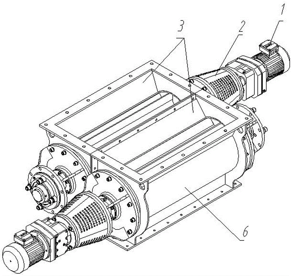
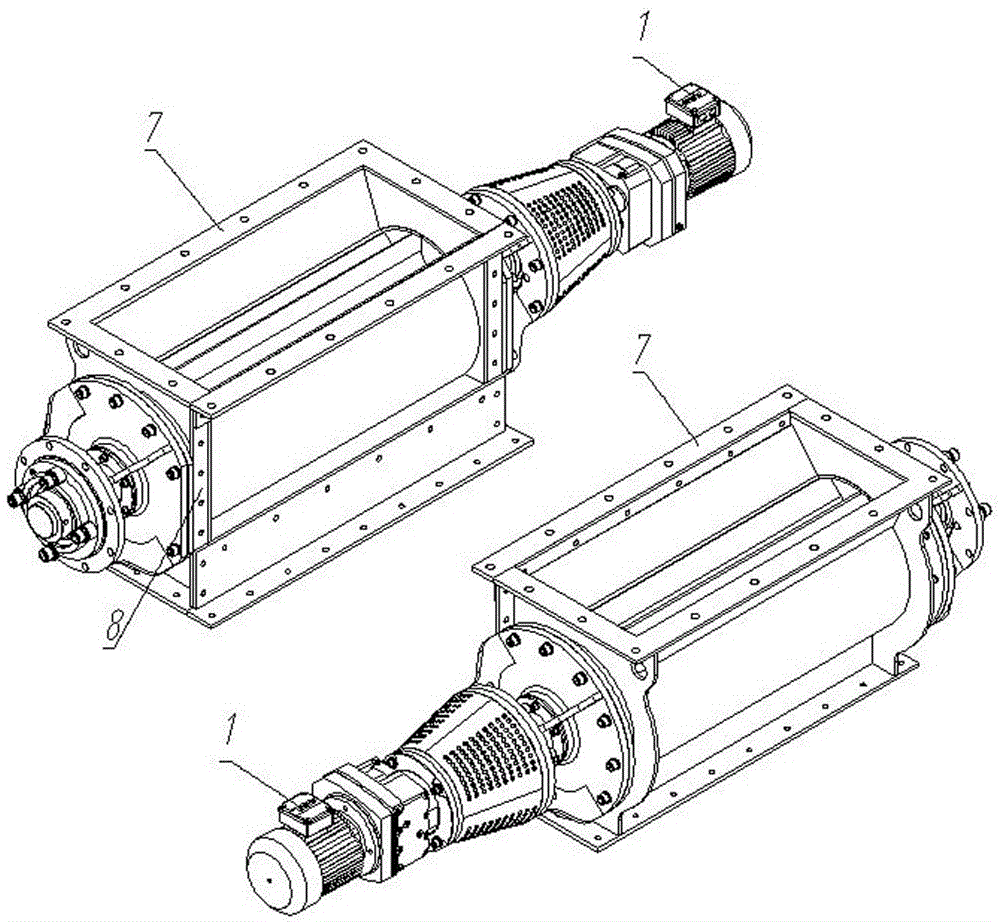
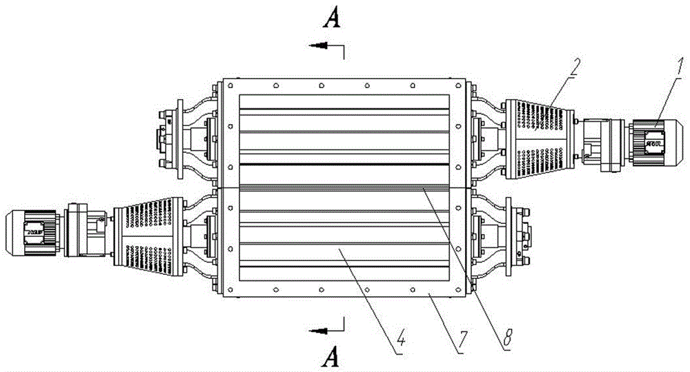
[0025] See figure 1 , figure 2 , image 3 , Figure 4 , Figure 5 , Including two rotary air lock valves, the two rotary air lock valves are symmetrically arranged and connected by a connecting flange as a whole; each rotary air lock valve includes a power drive device 1, an elastic coupling 2, a housing 6, Impeller, the impeller includes a rotor 5 and blades 4. The power drive device 1 is connected to the rotor 5 through an elastic coupling 2 to control the rotation of the rotor 5. A plurality of blades 4 are fixed around the rotor 5, and the casing 6 is mounted on the impeller 4 On the periphery, every two blades 4 and the casing 6 form a cavity, and the upper and lower ends of the casing 6 are respectively provi...


PUM


Abstract

The invention relates to a rotary air locking valve, in particular to a multifunctional detachable type double-impeller rotary air locking valve device comprising two rotary air locking valves; the two rotary air locking valves are arranged symmetrically and connected to be a whole through a connecting flange; each rotary air locking valve comprises a power driving device, an elastic coupler, a shell and a impeller; each impeller comprises a rotor and vanes; each power driving device is connected with each rotor through the corresponding elastic coupler; the multiple vanes are fixed around each rotor; each shell is mounted on the periphery of the corresponding impeller; every two vanes and the corresponding shell form a containing cavity; and a feeding inlet and a discharging outlet are correspondingly formed in the upper end and the lower end of each shell. By means of the double impellers, the material processing capacity of the two containing cavities is large, and the large discharging processing capacity can be achieved without increasing of the area of the impeller; the height of a rotary discharging device is reduced effectively, and the multifunctional detachable type double-impeller rotary air locking valve device can be applied to a structure of compact space; and replacement and maintenance are convenient, a fault machine can be detached alone, machine halting for a long time is not needed, and continuous production is guaranteed.

Description

Technical field [0001] The invention relates to a rotary air lock valve, in particular to a multi-purpose detachable double impeller rotary air lock valve device. Background technique [0002] In the case of a constant driving motor speed, the larger the volume of the cavity formed between each grid of the impeller and the casing, the greater the feeding capacity of the rotary air lock valve. By increasing the driving motor speed, the feeding can also be increased If the speed exceeds a certain range, the cutting will be insufficient. Within the reasonable speed range of the motor, the diameter of the impeller is increased to increase the cavity to meet the requirements of the cutting capacity. This method leads to the volume of the rotary blanker Increase and height increase, and it is easy to interfere with other structures in a compact space, which makes it impossible to install and use. At the same time, it needs to add multiple rotary air lock valves and corresponding device...

Claims


Application Information

Patent Timeline
Patent Type & Authority Applications(China)
IPC IPC(8): B65G29/00B65G53/46
CPCB65G29/00B65G53/4608
Inventor 陶瑛史可心刘艾明王强申金永刘剑英曹新明王晖郭腾云马峥嵘
Owner CBMI CONSTR
Learn More