Crack-relief layer sheet positioning pressure-bonding and winding take-up and unwinding device of the coating machine

A technology of positioning device and anti-cracking layer, which is applied in the direction of lamination device, lamination, transportation and packaging, etc. It can solve the problem of many air bubbles on the surface of the composite backplane and the cracked layer material, uneven bullet-proof inserting board surface, Reduce production efficiency and other issues, achieve consistent results, eliminate slippage, and improve work efficiency

Active Publication Date: 2018-01-30
JIHUA 3502 PROFESSIONAL GARMENT
View PDF6 Cites 0 Cited by
  • Summary
  • Abstract
  • Description
  • Claims
  • Application Information

AI Technical Summary

Problems solved by technology

But at present, in the bonding of the anti-crack layer materials on the bullet-proof surface of the bulletproof board, it is necessary to brush glue on the anti-crack layer materials, and then align the anti-bullet surface of the composite backboard with the anti-crack layer materials, and then manually Rolling hard is not only labor-intensive, but also due to uneven force, there are many air bubbles between the surface of the composite backplane and the split layer material, which makes the bullet-proof surface of the finished bulletproof plate uneven, time-consuming and labor-intensive, and affects product quality. reduced productivity

Method used


Image

  • Crack-relief layer sheet positioning pressure-bonding and winding take-up and unwinding device of the coating machine
  • Crack-relief layer sheet positioning pressure-bonding and winding take-up and unwinding device of the coating machine
  • Crack-relief layer sheet positioning pressure-bonding and winding take-up and unwinding device of the coating machine

Examples


Embodiment Construction

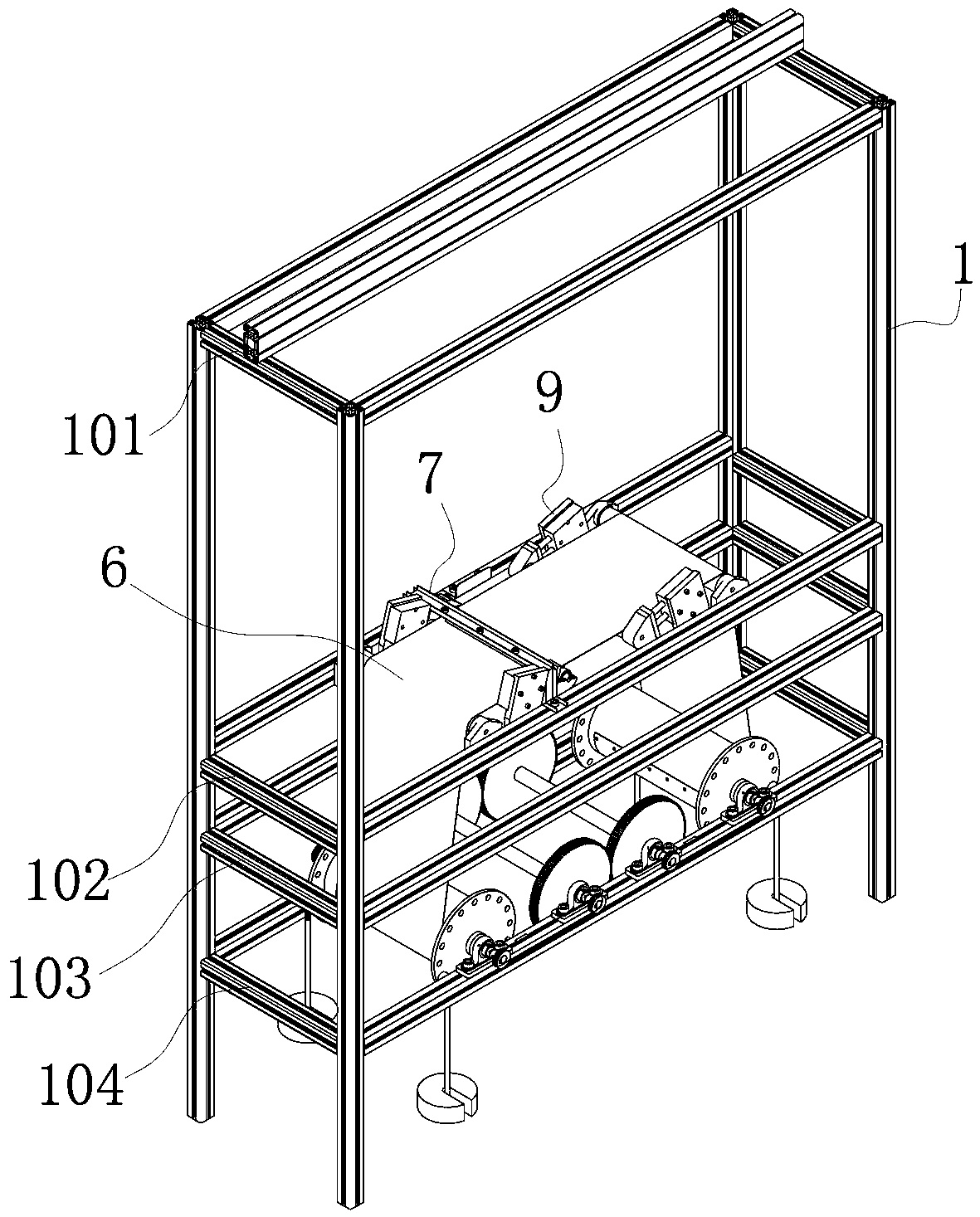
[0030] as attached figure 1 As shown, the present invention includes a frame, a winding belt synchronous tape release and take-up device 6, a crack arresting layer sheet positioning device 7, and a composite backboard pressure-bonding device 9; the frame includes a frame body 1, and the frame body 1 includes a set The upper frame 101 at the top, the middle frame 102 arranged in the middle, the bottom frame 104 arranged at the bottom, and the attached frame 103 arranged between the middle frame 102 and the bottom frame 104; The bottom is fixedly installed on the bottom frame 104, the top of the winding belt synchronous unwinding and taking-up device 6 is fixedly installed on the middle frame 102, and the crack arresting layer sheet positioning device 7 is installed on the middle frame 102 and is located at the winding belt synchronous Above the tape release and take-up device 6 , the composite backboard pressure-bonding device 9 is located inside the top of the winding tape syn...


PUM


Abstract

The invention relates to a crack-stopper layer material slice positioning press-bonding and wrapping belt take-up and pay-off device of a sheathing machine. The device comprises a rack, a wrapping belt synchronous take-up and pay-off device, a crack-stopper layer material slice positioning mould and a composite backboard press-bonding device. The bottom of the wrapping belt synchronous take-up and pay-off device is fixedly mounted on a bottom framework; the top of the wrapping belt synchronous take-up and pay-off device is fixedly mounted on a middle framework; a crack-stopper layer material slice positioning device is mounted on the middle framework; and the composite backboard press-bonding device is located on the inner side of the top of the wrapping belt synchronous take-up and pay-off device. The sheathing machine with the crack-stopper layer material slice positioning press-bonding and wrapping belt take-up and pay-off device is used for adhering a composite backboard bullet-facing surface and a crack-stopper layer material slice. Operation is easy. Positioning is accurate. Automatic operation is achieved. The adhesion surface is smooth. Entire edges and corners are clear after product finishing, and time and efforts are saved as well as the adhesion is firm. The working efficiency is improved. The product quality is guaranteed. The crack-stopper layer material slice positioning press-bonding and wrapping belt take-up and pay-off device is suitable for application and popularization in equipment and fitting enterprises.

Description

technical field [0001] The invention relates to a device for positioning, pressure-bonding, winding, retracting and unwinding of a crack arresting layer sheet of a cladding machine, and belongs to the technical field of production and processing machinery for armor-like bulletproof products. Background technique [0002] In equipment manufacturing enterprises, especially the production of new military bulletproof panels is relatively large. The outer protective layer of the bulletproof panel is made by bonding the bullet-facing surface and the rear surface of the composite backplane with the crack arresting layer material. The composite backplane The bullet-facing surface, that is, the convex surface, is made of silicon carbide, which is called wood ceramics by the military, and it is about 7mm thick. It is about 7mm thick, and the anti-crack layer sheets on the front and rear sides of the composite backplane are all single-layer PE cloth; the length of the composite backpla...

Claims


Application Information

Patent Timeline
Patent Type & Authority Patents(China)
IPC IPC(8): B65H23/16B65H16/06B32B37/10B32B37/12B32B38/18
CPCB32B37/10B32B37/1284B32B38/1841B65H16/06B65H23/16
Inventor 马永树李海涛王建新程琳
Owner JIHUA 3502 PROFESSIONAL GARMENT
Why Eureka
Try Eureka