Engine block of an internal combustion engine

A technology of engine block and internal combustion engine, applied in the direction of machine/engine, engine element, cylinder, etc., can solve the problem of difficult design of cylindrical area, and achieve the effect of small cutting work.

Pending Publication Date: 2017-04-26
BAYERISCHE MOTOREN WERKE AG
View PDF8 Cites 0 Cited by
  • Summary
  • Abstract
  • Description
  • Claims
  • Application Information

AI Technical Summary

Problems solved by technology

However, especially the shape of the lower c

Method used


Image

  • Engine block of an internal combustion engine
  • Engine block of an internal combustion engine
  • Engine block of an internal combustion engine

Examples


Embodiment Construction

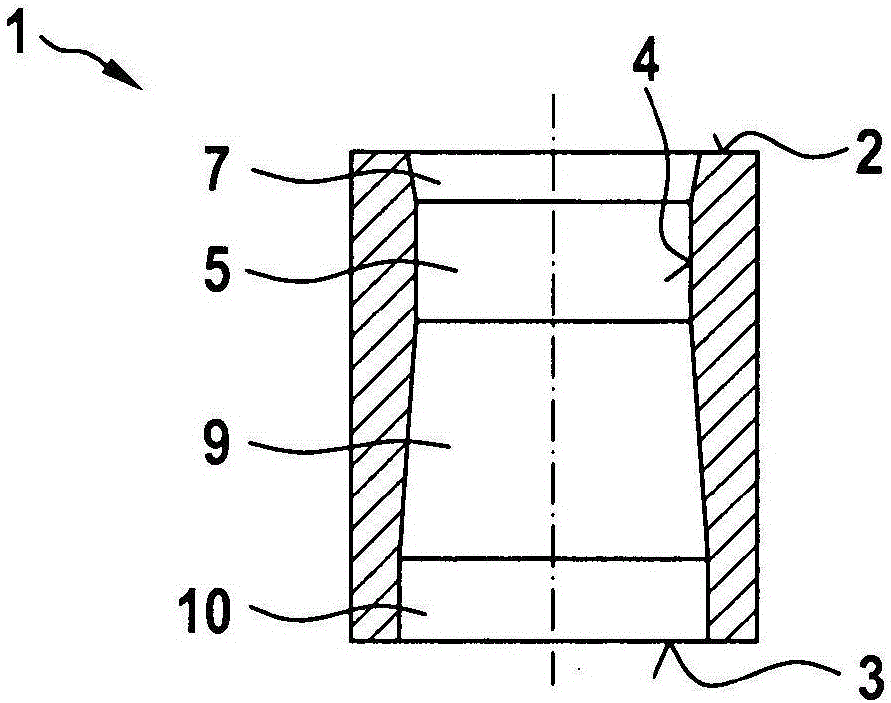
[0034] figure 1 The engine block 1 according to the first exemplary embodiment is shown schematically. The engine block 1 has cylinders, which are represented by cylinder bores 4 . The cylinder bore 4 extends between the upper end 2 and the lower end 3 . In this case, the upper end 2 corresponds to that end onto which the cylinder head can be placed. The lower end 3 corresponds to that end onto which the crankcase can be placed. A piston can be arranged within the cylinder bore 4 , which can move up and down within the cylinder bore 4 in order to operate the internal combustion engine.

[0035] The cylinder bore 4 has a larger diameter than the smallest diameter in the region between the lower end 3 and a boundary which is at most 70%, preferably at most 60% of the distance between the upper end 2 and the lower end 3 from the upper end 2 %, particularly preferably up to 50%. Furthermore, it is provided that the diameter in this region increases at least in places towards ...


PUM


Abstract

The invention relates to an engine block (1) of an internal combustion engine; the engine block comprises at least one cylinder, wherein a cylinder hole for a piston of the internal combustion engine extends between an upper end (2) and a lower end (3), wherein the cylinder hole (4) is formed by a piston (11) at the lower end (3), and wherein a diameter of the cylinder hole (4) extends over the lower bell-shaped expansion region (11) in the region of the lower bell-shaped expansion region (11) Direction of the lower end (3) increases continuously non-linearly.

Description

technical field [0001] The invention relates to an engine block of an internal combustion engine. The invention relates in particular to the shaping of the cylinder bores of the cylinders of the engine block. Background technique [0002] Engine blocks are known from the prior art. Such engine blocks have cylinder bores in which pistons of the internal combustion engine can be guided. It is known from the prior art to produce such bores cylindrically. [0003] However, a cylindrical bore has the disadvantage that the frictional power of the piston increases. Consequently, the geometry of the cylinder bores mostly changes when the cylinder head is installed and / or the engine block is heated by the operation of the internal combustion engine. Different expansions of the engine block can also be caused, inter alia, by the fact that the water cooling only cools a subregion of the engine. As a result, the originally cylindrical bore is deformed, whereby the frictional power ...

Claims


Application Information

Patent Timeline
IPC IPC(8): F02F1/18
CPCF02F1/18
Inventor C·皮希勒J·绍布迈尔
Owner BAYERISCHE MOTOREN WERKE AG
Why Eureka
Try Eureka