Automobile transmission exhaust device

A technology for automotive transmissions and exhaust devices, which is applied to transmission parts, belts/chains/gears, mechanical equipment, etc. It can solve problems such as corrosion, transmission function failure, and high energy consumption of the transmission, so as to achieve good anti-pollution effect and improve The effect of service life

Pending Publication Date: 2017-04-26
CHONGQING TSINGSHAN IND
View PDF12 Cites 4 Cited by
  • Summary
  • Abstract
  • Description
  • Claims
  • Application Information

AI Technical Summary

Problems solved by technology

The existing technical problem of the automotive transmission exhaust device of this structure is that the inside of the transmission case body 2 is connected with the outside through the exhaust passage 11 of the exhaust plug 1, and the oil vapor inside the transmission case body 2 will directly pass through. The lower end of the exhaust plug body 10 through the exhaust plug 1 enters the exhaust channel 11, and then volatilizes from the exhaust channel 11 to the outside of the transmission case 2 by both sides of the upper end of the exhaust plug body 10, as figure 1 As shown by the dotted arrow in the middle, the energy consumption of the automobile transmission is more
At the same time, dust, dirt particles or moisture in the external atmosphere may figure 1 The direction opposite to the arrow in the dotted line enters the exhaust passage 11 from both sides of the upper end of the exhaust plug body 10 of the exhaust plug 1, and then enters the transmission case 2 from the lower end of the exhaust plug body 10 through the intake and exhaust passage 11. Internally, the lubricating oil in the transmission case 2 will fail or the internal parts will be corroded, and the anti-pollution effect will be poor. If this happens for a long time, it will lead to the failure of the transmission function

Method used


Image

  • Automobile transmission exhaust device
  • Automobile transmission exhaust device
  • Automobile transmission exhaust device

Examples


Embodiment Construction

[0023] Preferred embodiments of the present invention will be described in detail below in conjunction with the accompanying drawings.

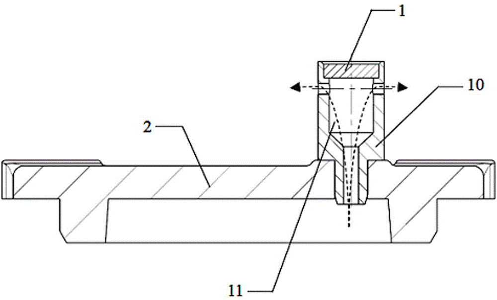
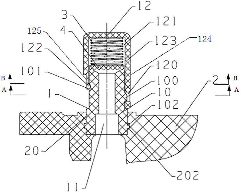
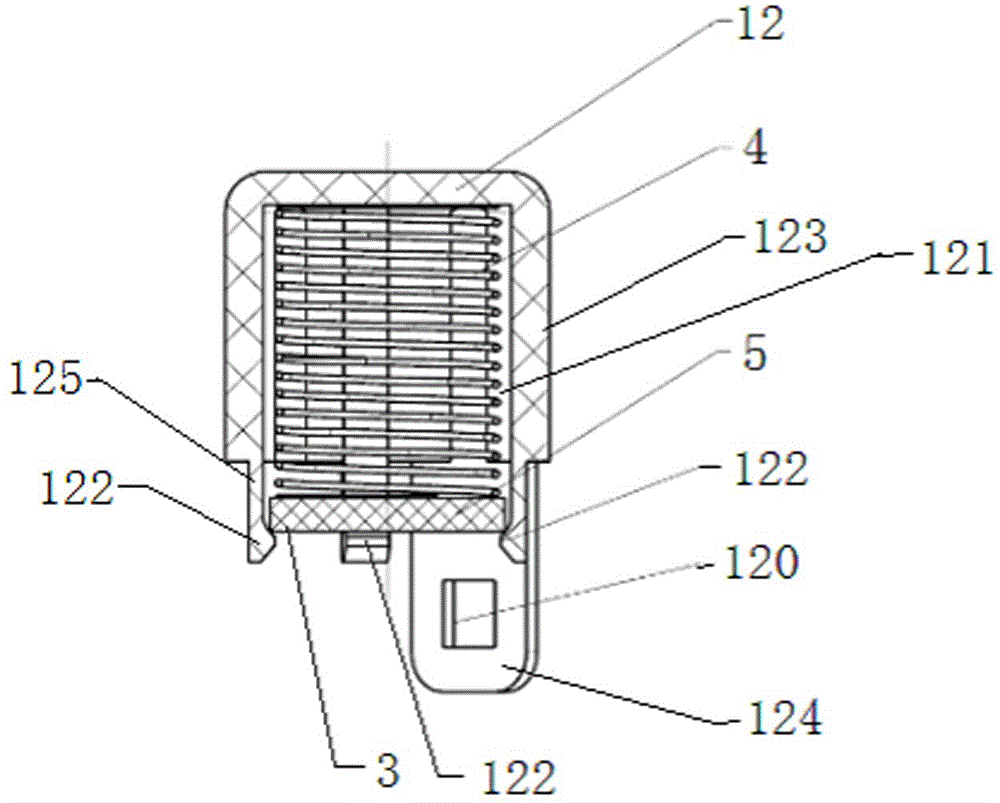
[0024] see Figures 2 to 5 , the automobile transmission exhaust device of the present invention, comprises exhaust plug 1, and described exhaust plug 1 comprises the exhaust plug body 10 that lower end is connected with transmission box 2 and is positioned at the outside of transmission box body 2, and by exhaust plug body 10 The lower end of the lower end communicates with the inside of the transmission case 2. The exhaust passage 11. Depend on Figures 2 to 5It can be seen that the present invention also includes the exhaust plug cover 12 made of elastic material, the spring 3 and the barrier piece 4, and the snap-in structure 120, 100. The exhaust plug cover 12 includes an exhaust plug cover with a lower end opening The exhaust plug cover 123 of the cavity 121, the exhaust channel 11 in the exhaust plug body 10 of the exhaust plug 1 run...


PUM


Abstract

The invention provides an automobile transmission exhaust device low in energy consumption. An exhaust channel in an exhaust plug body of an exhaust plug penetrates through the upper end and the lower end of the exhaust plug body. The inner diameter of an exhaust plug cover cavity of an exhaust plug cover is slightly larger than the outer diameter of the exhaust plug body of the exhaust plug. A clamping structure comprises at least two clamping connecting parts, at least two clamping parts and at least two matching clamping parts, wherein the clamping connecting parts extend downwards from the lower end of the exhaust plug cover cavity of the exhaust plug cover, the clamping parts are arranged on the clamping connecting parts correspondingly, and the matching clamping parts are correspondingly arranged on the periphery of the exhaust plug body of the exhaust plug. The exhaust plug cover cavity of the exhaust plug cover is clamped with the exhaust plug body of the exhaust plug through the clamping parts and the matching clamping parts, and a first clearance exists in the position, outside the clamping position, between the part in the circumferential direction of the exhaust plug cover cavity of the exhaust plug cover and the part in the circumferential direction of the exhaust plug body of the exhaust plug. A spring and a spacing piece are placed between the exhaust plug cover cavity and the exhaust plug in an up-down mode, and the diameter of the spacing piece is larger than the inner diameter of the upper portion of the exhaust channel and is smaller than the inner diameter of the exhaust plug cover cavity.

Description

technical field [0001] The invention relates to an automobile transmission, in particular to an exhaust device for an automobile transmission. Background technique [0002] Those skilled in the art know that when the automobile transmission is working, the temperature of the oil in the transmission case will change with the change of the internal air volume caused by the operation of various gears and other moving parts in the transmission case. The air pressure and temperature in the air will be different from the external atmospheric pressure and atmospheric temperature, which is the so-called pumping effect. This pumping effect consumes energy. In order to reduce this part of energy consumption, the automobile transmission is usually equipped with an exhaust device that connects the inside and outside of the transmission case. The outside atmosphere is kept in balance, so as to ensure the normal operation of the transmission; the second is to block the dust, dirt partic...

Claims


Application Information

Patent Timeline
Patent Type & Authority Applications(China)
IPC IPC(8): F16H57/027
CPCF16H57/027F16H2057/02043
Inventor 侯淼洪波夏丽华王鑫杨大学陈超超周云峰王玉强何俊谋
Owner CHONGQING TSINGSHAN IND
Why Eureka
Try Eureka