
Measuring device and measuring method for surrounding rock deformation of geotechnical model test

A model test and surrounding rock deformation technology, which is applied in the direction of measuring devices, optical devices, instruments, etc., can solve the problems that the measuring device cannot be uploaded to the computer in time, the change of surrounding rock cannot be accurately measured, and the effective measurement cannot be carried out. , to achieve the effect of timing automatic measurement, saving labor intensity and realizing repeated measurement

Inactive Publication Date: 2017-04-26
SHANDONG UNIV
View PDF8 Cites 7 Cited by
  • Summary
  • Abstract
  • Description
  • Claims
  • Application Information

AI Technical Summary

Problems solved by technology

[0006] 1. The general measurement device has low precision and poor timeliness, and cannot accurately measure the change of surrounding rock
[0007] 2. For the experimental device with simulated narrow tunnel, effective measurement cannot be carried out;
[0008] 3. The measuring device cannot be uploaded to the computer in time, or the data cannot be automatically uploaded, resulting in a heavy workload and a lot of gross errors

Method used


Image

  • Measuring device and measuring method for surrounding rock deformation of geotechnical model test
  • Measuring device and measuring method for surrounding rock deformation of geotechnical model test
  • Measuring device and measuring method for surrounding rock deformation of geotechnical model test

Examples


Embodiment Construction

[0041] The present invention will be further described below in conjunction with the accompanying drawings and embodiments.

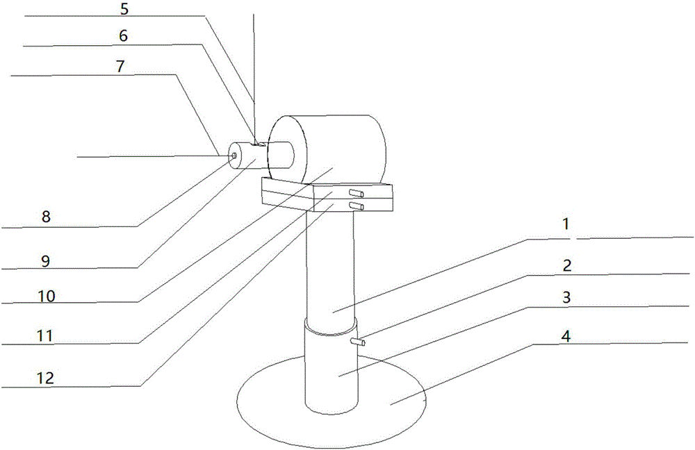
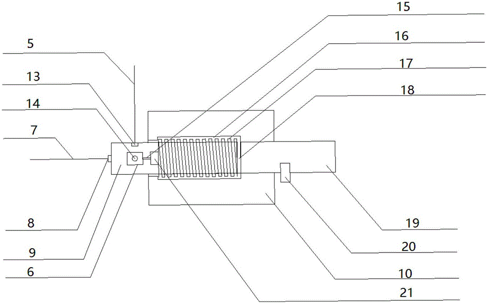
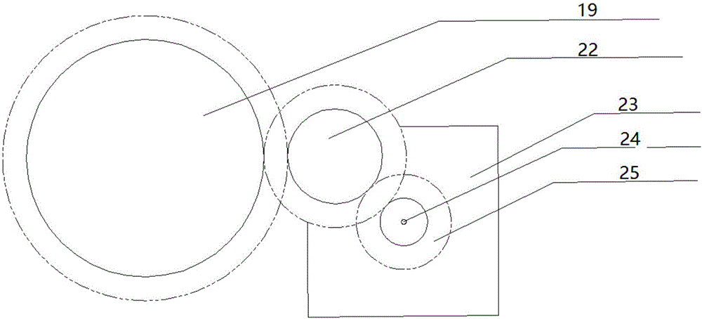
[0042] Such as figure 1 As shown, a surrounding rock deformation measurement device for geotechnical model tests includes a limit mechanism, a transmission rod, a laser ranging mechanism, a laser calibration mechanism, a laser limit mechanism, a transmission device, a fixing device, and a multi-axis displacement fine-tuning device , signal transmission device and control device; the transmission rod is on the limit mechanism; the laser ranging mechanism, laser calibration mechanism and laser limit mechanism are placed in the front of the transmission rod, and the rear of the transmission rod The part is connected with the transmission device, the limit mechanism is on the fixing device, and the multi-axis displacement fine-tuning device is placed on the fixing device.

[0043] The central axis of the laser transmitter of the laser ranging mechanism pas...


PUM


Abstract

The invention discloses a measuring device and a measuring method for surrounding rock deformation of a geotechnical model test. The measuring device comprises a spacing mechanism, an elevating mechanism, a transmission rod, a laser distance measuring mechanism and a laser calibrating mechanism, wherein the elevating mechanism is provided with the spacing mechanism. The transmission rod is arranged at the front end of the spacing mechanism. The front end of the transmission rod is provided with the laser distance measuring mechanism and the laser calibrating mechanism. The axis of the laser transmitter of the laser distance measuring mechanism passes is crossed with the axis of the transmission rod and is perpendicular with the same. The laser transmitter of the laser calibrating mechanism is arranged at the axis position of the transmission rod. The laser mechanism and the laser ranging mechanism are in one plane which is perpendicular with the axis of the transmission rod. According to the measuring device and the measuring method, surrounding rock deformation detection can be efficiently performed by means of the laser distance measuring mechanism, and a high-precision result of a surrounding rock deformation simulation test in a tunnel excavation process is obtained.

Description

technical field [0001] The invention relates to the field of civil engineering, in particular to a surrounding rock deformation measurement device and a measurement method for geotechnical model tests. Background technique [0002] my country is already the country with the largest scale and difficulty in tunnel construction in the world. In the face of various complex geological conditions in tunnel construction, different construction methods need to be combined with reality. Geotechnical model tests can simulate the surrounding rock changes during tunnel construction under certain circumstances, and have many advantages such as high efficiency, economy, and high degree of simulation. More and more tunnel construction in my country will refer to the results of geotechnical model tests. Displacement or deformation is the result of the interaction between the mechanical properties of the surrounding rock in geotechnical engineering and the stress environment in which it is l...

Claims


Application Information

Patent Timeline
Patent Type & Authority Applications(China)
IPC IPC(8): G01B11/16
CPCG01B11/16
Inventor 李术才秦承帅石少帅王康刘洪亮贺鹏周申
Owner SHANDONG UNIV
Learn More