
Integrated power distribution cabinet

An integrated technology for power distribution cabinets, applied in the field of power distribution boxes, can solve problems such as cable crossing confusion, long operation time, and potential safety hazards, and achieve increased heat dissipation, high disassembly and assembly convenience, and improved use safety Effect

Active Publication Date: 2021-06-18
山东科美帝电气科技有限公司
View PDF12 Cites 0 Cited by
  • Summary
  • Abstract
  • Description
  • Claims
  • Application Information

AI Technical Summary

Problems solved by technology

[0004] In view of this, the present invention addresses the deficiencies in the prior art, and its main purpose is to provide an integrated power distribution cabinet to solve the problem that most of the current distribution cabinets mentioned in the above background have simple structures and are usually made of metal. The box structure is equipped with installation brackets for electrical equipment such as switches. During installation and cable arrangement, due to the lack of cable restraint mechanism, electric workers need to manually arrange and arrange the cables during the installation and arrangement process. Fixed, the operation time is long and it is easy to cause cable crossing and confusion. At the same time, some electrical equipment will generate heat when in use. Lack of active heat dissipation mechanism, heat is easy to accumulate inside the distribution box, causing safety hazards

Method used


Image

  • Integrated power distribution cabinet
  • Integrated power distribution cabinet
  • Integrated power distribution cabinet

Examples


Embodiment Construction

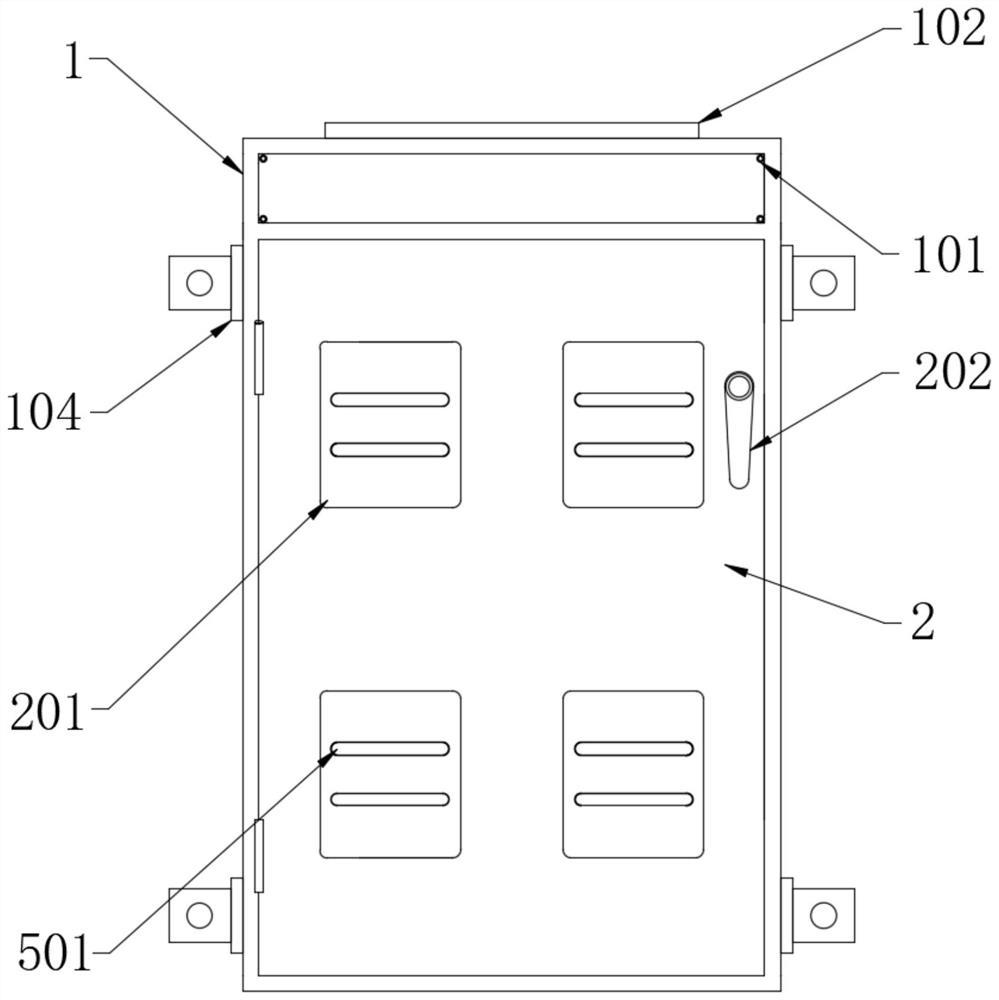
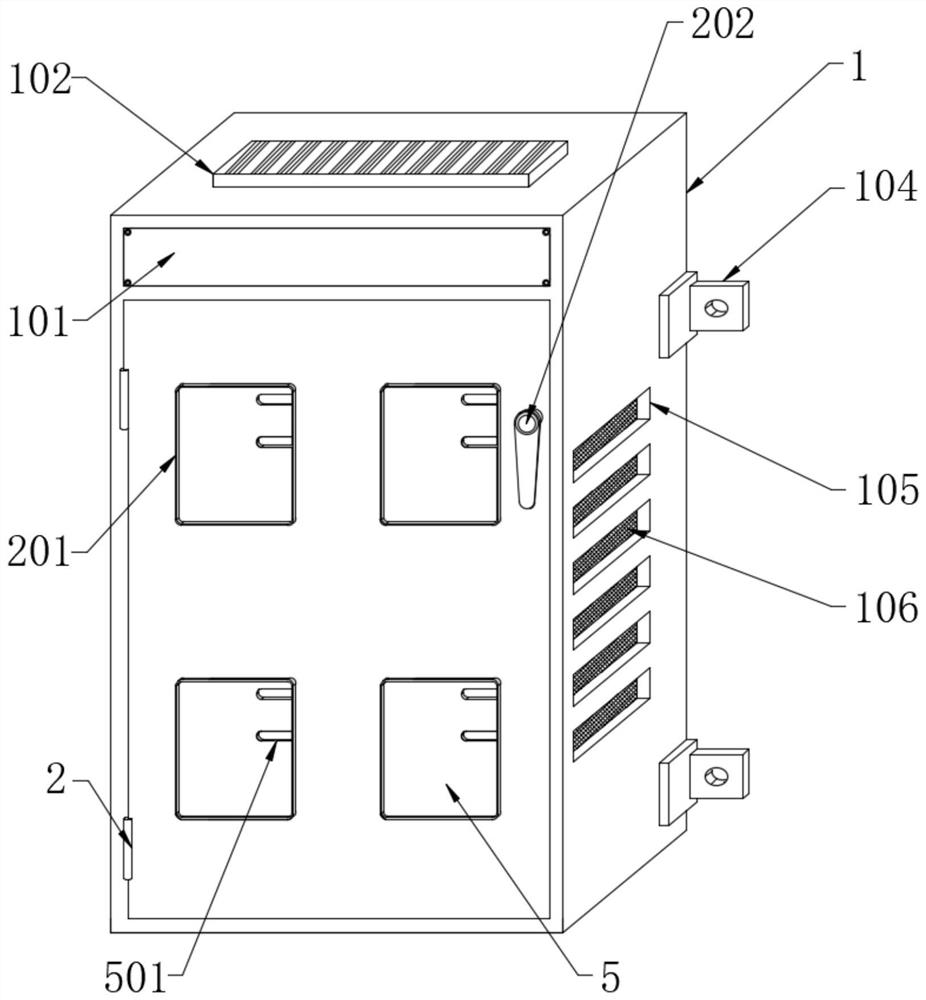
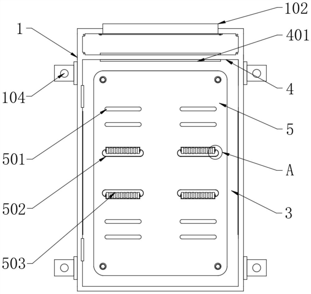
[0033] Please refer to Figure 1 to Figure 10As shown, it shows the specific structure of the preferred embodiment of the present invention, an integrated power distribution cabinet, including a box body 1, a vertical partition 3 and a mounting plate 5, the front side of the box body 1 is installed with The box door 2, and the box body 1 is a hollow cubic structure; the vertical partition 3 is installed inside the box body 1, and a horizontal partition 4 is installed on one side of the box body 1, and the vertical partition 3 cooperates with the horizontal partition The partition board 4 divides the interior of the box body 1 into three independent spaces; the mounting plate 5 is installed on the side of the vertical partition board 3 close to the box door 2, and the connection mode between the installation board 5 and the vertical partition board 3 is a card combined connection.

[0034] Specifically, by opening a plurality of independent spaces in the box body 1, the circui...


PUM


Abstract

The invention discloses an integrated power distribution cabinet, which comprises a box body, a vertical partition plate and a mounting plate, and is provided with a fixing clamp, a first elastic sheet and a second elastic sheet push two clamping rings to turn outwards under the effect of self elastic force, so that a cable only needs to be plugged between the two clamping rings when being fixed, and when the cable is plugged between the two clamping rings, the two clamping rings are driven to turn towards the interior of the fixing clamp and extrude a first elastic piece and a second elastic piece until the tail ends of the two clamping rings are clamped with the two ends of the clamping spring of the M-shaped structure, and at the moment, the two clamping rings are matched with the clamping spring to tightly wrap an outer protection layer of the cable. Firstly, the structure is simple, the operation difficulty is low, the occupied equipment internal space is small, and the production cost is low; and secondly, internal structures can be communicated with each other, after fixation is completed, the clamping spring can effectively prevent the two clamping rings from expanding outwards, the compressed first elastic piece and the compressed second elastic piece can push the clamping rings to be tightly attached to the clamping spring, and it is ensured that the cable is not prone to falling off after being fixed.

Description

technical field [0001] The invention relates to the related technical field of distribution boxes, in particular to an integrated distribution cabinet. Background technique [0002] Distribution box is usually assembled in closed or semiclosed metal safe by switchgear, measuring instrument, protective device and auxiliary equipment or on screen width, forms low-voltage distribution box, can turn on or off by manual or automatic switch during normal operation. The circuit and distribution box have the characteristics of small size, easy installation, special technical performance, fixed position, unique configuration function, not limited by the site, common application, stable and reliable operation, high space utilization rate, less land occupation and environmental protection effect . [0003] However, most of the distribution boxes currently in use have a simple structure, usually a box structure made of metal, with mounting brackets for electrical equipment such as swit...

Claims


Application Information

Patent Timeline
Patent Type & Authority Applications(China)
IPC IPC(8): H02B1/56H02B1/28H02B1/20H02B1/30H02B1/32H02G3/04
CPCH02B1/565H02B1/28H02B1/202H02B1/306H02B1/32H02G3/045
Inventor 杨胜正
Owner 山东科美帝电气科技有限公司
Learn More