Temperature measurement device of cable joint and cable joint

A technology of cable joints and temperature measuring devices, which is applied in the direction of measuring devices, parts of connecting devices, coupling devices, etc., and can solve problems such as excessive volume, low temperature resistance insulation performance, and complicated installation

Pending Publication Date: 2017-04-26
廊坊芳远新合电气股份有限公司 +1
View PDF2 Cites 8 Cited by
  • Summary
  • Abstract
  • Description
  • Claims
  • Application Information

AI Technical Summary

Problems solved by technology

[0002] Most of the safety accidents in the power distribution industry of my country's power system are caused by the heating of the connection points in the cabinet. Whether it is an active wired non-contact or a passive wired contact, there are problems of one kind or another, such as interference by the surrounding environment and elec

Method used


Image

  • Temperature measurement device of cable joint and cable joint
  • Temperature measurement device of cable joint and cable joint
  • Temperature measurement device of cable joint and cable joint

Examples


Embodiment 1

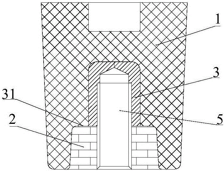
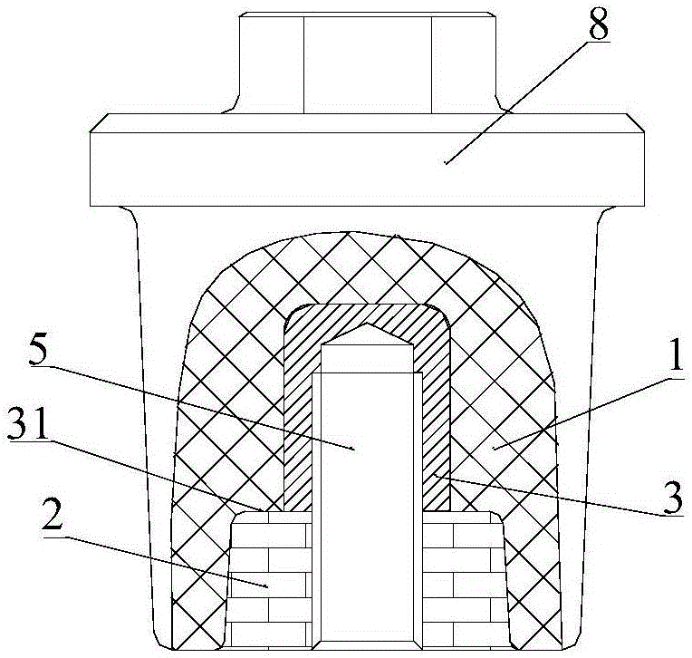
[0034] Such as figure 1 As shown, a temperature measuring device for a cable connector of this embodiment includes a rear plug cover 1 and a temperature measuring sensor device 2. One end of the back plug cover 1 is embedded with a metal insert 3, and the cable connector is wired The terminal 4 is fixedly connected to the metal insert 3, and the temperature sensing device 2 is crimped between the connection terminal 4 and the metal insert 3;

[0035] The temperature sensing device 2 is a SAW temperature sensor or a radio frequency identification sensor or a radio frequency sensor that can be powered by an electric field. The radio frequency identification sensor is a sensor that can work normally without external voltage. The radio frequency sensor that relies on electric field for electricity must have an external voltage to work, and the external voltage is above 2KV. In this embodiment, by directly contacting the heating point inside the cable joint through the temperature sen...

Embodiment approach

[0038] There are multiple implementations of the rear plug cover of this embodiment, which are specifically as follows:

Embodiment approach 1

[0039] Implementation mode one: such as Figure 1-Figure 3 As shown, in this embodiment, the rear plug cover 1 has a cylindrical structure with one end blocked, the metal insert 3 is inserted and fixed to the open end of the rear plug cover 1, and the rear plug cover 1 is open. An annular step 12 is provided on the inner ring side of the end, and the annular step 12 is flush with the end of the metal insert 3; the temperature sensing device 2 is sleeved on the stud bolt by interference fit 5, one end of which is crimped on the annular step 12 and the metal insert 3, and the other end is flush with the open end of the rear plug cover 1. By crimping the temperature measuring sensor device on the annular step and the metal insert, the overall fixing is firmer.

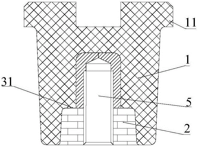
[0040] The rear blocking cover 1 of this embodiment may be a cylindrical shape with a smooth outer wall, such as figure 1 As shown; it is also possible to set a circumferentially arranged outer edge 11 on the outer wall of t...


PUM


Abstract

The present invention relates to a temperature measurement device of a cable joint and a cable joint. The temperature measurement device comprises a rear plugging cover and a temperature measurement sensing device; a metal insert is embedded into one end of the rear plugging cover; the wiring terminal of the cable joint is fixedly connected with the metal insert; the temperature measurement sensing device is crimped between the wiring terminal and the metal insert; and the temperature measurement sensing device is an SAW temperature sensor or a radio frequency identification sensor or a radio frequency sensor which obtains electricity through an electric field. According to the temperature measurement device of the cable joint of the invention, the temperature measurement sensing device directly contacts with a heat emitting point in the cable joint, so that the temperature of a cable connection point in the cable joint can be reflected effectively and authentically.

Description

Technical field [0001] The invention relates to the field of temperature measurement of cable joints in power equipment, in particular to a temperature measurement device for real-time monitoring of the internal conductor temperature of the cable joint of the power equipment by wireless passive contact, and a cable joint including the temperature measurement device. Background technique [0002] Most of the safety accidents in the power distribution industry in our country are caused by the heating of the connection points in the cabinet. Therefore, to avoid and reduce the occurrence of accidents, it is mainly to know the temperature change and temperature value of the contact in advance. However, the existing measurement The temperature method, whether it is active wired non-contact or passive wired contact, has problems of one kind or another, such as being interfered by the surrounding environment and electromagnetic field, being too large, fragile and easy to break, complex in...

Claims


Application Information

Patent Timeline
IPC IPC(8): G01K11/26H01R13/66
CPCH01R13/6683G01K11/265
Inventor 张玉龙王建新张淑琴刘丽强
Owner 廊坊芳远新合电气股份有限公司
Why Eureka
Try Eureka