Heat dissipation electrical cabinet with electrical automatic control and alarm system thereof

A technology of electrical automation and electrical cabinets, which is applied in the direction of alarms, electrical components, substation/power distribution device shells, etc., which can solve the problems of electrical components damage, waste, energy consumption, etc. in electrical cabinets, achieve safe and convenient use, and prolong discharge time , Structural scientific and reasonable effect

Active Publication Date: 2021-03-19
NANCHANG INST OF TECH
View PDF8 Cites 4 Cited by
  • Summary
  • Abstract
  • Description
  • Claims
  • Application Information

AI Technical Summary

Problems solved by technology

[0004] The present invention provides a heat dissipation electrical cabinet controlled by electrical automation and its alarm system, which can effectively solve the general needs of the existing electrical cabinets in the above background technology during operation. The interior of the electrical cabinet is cooled by the heat dissipation mechanism, and the electrical components inside the electrical cabinet will dissipate heat when it is running. At the same time, the electrical cabinet is also easily affected by the temperature of the external environment. Internal heat dissipation, and when the internal temperature of the electrical cabinet tends to normal temperature, the operation of multiple heat dissipation mechanisms will inevitably cause energy consumption and waste, and the existing electrical cabinet cannot be opened in time when the temperature is too high The heat dissipation mechanism will also easily cause damage to the electrical components inside the electrical cabinet

Method used


Image

  • Heat dissipation electrical cabinet with electrical automatic control and alarm system thereof
  • Heat dissipation electrical cabinet with electrical automatic control and alarm system thereof
  • Heat dissipation electrical cabinet with electrical automatic control and alarm system thereof

Examples


Embodiment

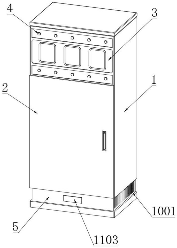
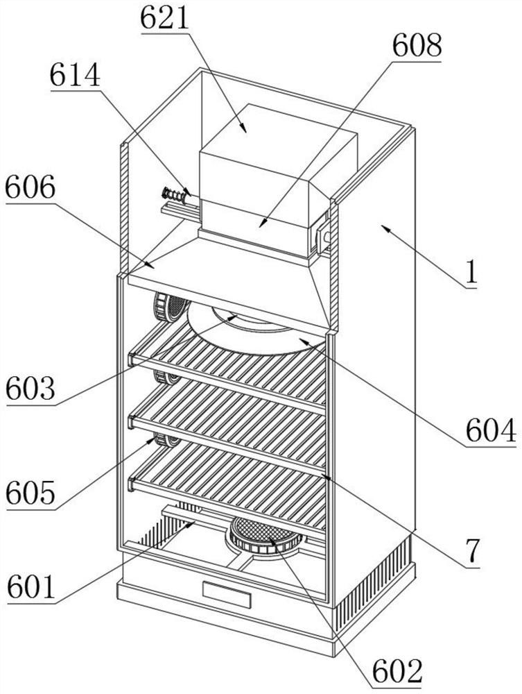
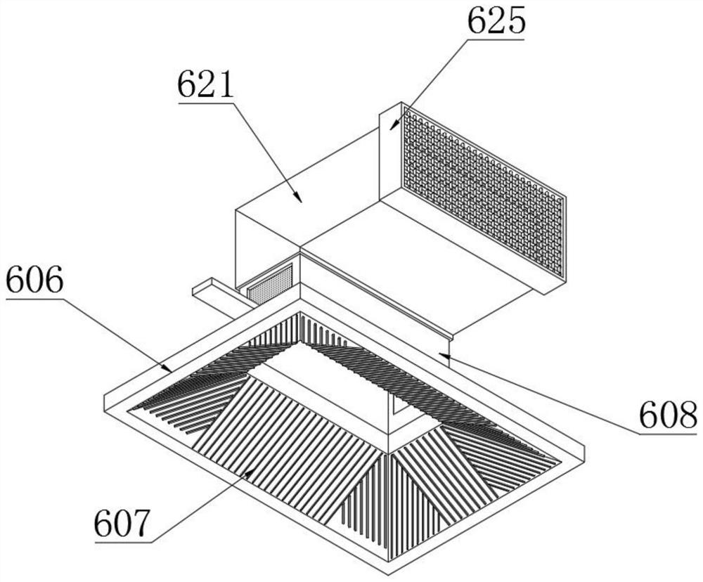
[0047] Example: such as Figure 1-8 As shown, the present invention provides a technical solution, a heat dissipation electrical cabinet controlled by electrical automation, including an electrical cabinet body 1, a cabinet door 2 is hinged on the outer end surface of the electrical cabinet body 1, and a display is embedded on the front end surface of the top of the electrical cabinet body 1. Panel 3, a warning light 4 is set at the side of the display panel 3, the bottom of the electrical cabinet body 1 is fixedly connected with a base 5, and an energy-saving heat dissipation component 6 is installed on the inside top of the electrical cabinet body 1, and the energy-saving heat dissipation component 6 includes a fan bracket 601, a second A cooling fan 602, a second cooling fan 603, a gas collecting hood 604, an auxiliary cooling fan 605, a heat collecting cone 606, a heat conducting metal strip 607, a heat collecting runner 608, a fixed bracket 609, a movable plate 610, and a ...


PUM


Abstract

The invention discloses a heat dissipation electrical cabinet with electrical automatic control. The electrical cabinet comprises an electrical cabinet body, a cabinet door is hinged to the end face of the outer side of the electrical cabinet body, a display panel is embedded in the front end face of the top of the electrical cabinet body, a warning lamp is arranged on the side of the display panel, a base is fixedly connected to the bottom of the electrical cabinet body, and an energy-saving heat dissipation assembly is installed at the top of the inner side of the electrical cabinet body. After a heat absorption expansion silica gel sheet is heated, a moving rod and an extrusion rod are pushed to move according to the thermal expansion principle, and a moving contact at the end of the extrusion rod can make direct contact with a contact switch when the extrusion rod moves. An auxiliary cooling fan is started by starting the contact switch. Therefore, on the basis of an original heatdissipation mechanism, an auxiliary heat dissipation mechanism in the electrical cabinet body can be automatically started when the temperature is too high, heat dissipation of the electrical cabinetbody is conveniently expanded, the electrical cabinet body can be self-regulated and controlled when facing different temperatures, and the purposes of energy conservation and consumption reduction are achieved.

Description

technical field [0001] The invention relates to the technical field of electrical equipment, in particular to a heat dissipation electrical cabinet controlled by electrical automation and an alarm system thereof. Background technique [0002] The electrical cabinet is made of steel to protect the normal operation of the components. The materials for the electrical cabinet are generally divided into two types: hot-rolled steel plate and cold-rolled steel plate. Compared with hot-rolled steel plate, cold-rolled steel plate is softer and more suitable for electrical appliances. The production of cabinets, electrical cabinets are widely used mainly in chemical industry, environmental protection industry, power system, metallurgical system, industry, nuclear power industry, fire safety monitoring, transportation industry, etc.; [0003] However, the existing electrical cabinet generally needs to cool its interior through a heat dissipation mechanism during operation, and the elec...

Claims


Application Information

Patent Timeline
Patent Type & Authority Applications(China)
IPC IPC(8): H02B1/56H02B1/28H02B1/30H02B1/32H02B1/04H02B1/01H02B1/50B01D53/26G08B5/36G08B21/24
CPCH02B1/565H02B1/28H02B1/306H02B1/32H02B1/04H02B1/012H02B1/50B01D53/263G08B5/36G08B21/24
Inventor 范莉夏非刘剑冰周正华
Owner NANCHANG INST OF TECH
Why Eureka
Try Eureka