
a generator

A generator and electrode technology, applied in the direction of friction generators, electromechanical devices, electrical components, etc., can solve the problems of low impact energy and small output charge

Active Publication Date: 2019-02-01
BEIJING INST OF NANOENERGY & NANOSYST
View PDF4 Cites 0 Cited by
  • Summary
  • Abstract
  • Description
  • Claims
  • Application Information

AI Technical Summary

Problems solved by technology

[0005] The embodiment of the present invention provides a generator, which is used to solve the problems of the existing triboelectric nanogenerators that the collected impact energy is less and the output charge is smaller

Method used


Image

  • a generator
  • a generator
  • a generator

Examples


Embodiment

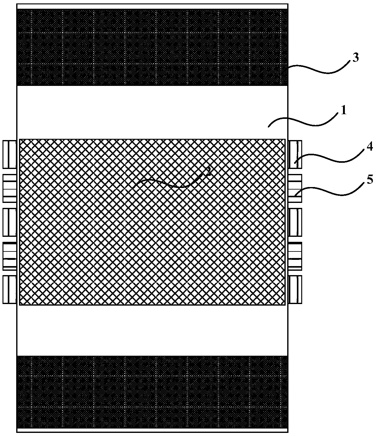
[0027] In order to solve the problems of the existing triboelectric nanogenerators that collect less impact energy and output a smaller amount of charge, an embodiment of the present invention provides a generator, such as figure 1 As shown, it is a longitudinal section view of the generator structure described in the embodiment of the present invention. Specifically, by figure 1 It can be seen that the generator may include a body 1 with a cavity, a mass 2, an elastic member 3, a first electrode 4 and a second electrode 5, wherein:

[0028] The mass block 2 is arranged in the cavity of the body 1 and can be used to strike the body 1 and the elastic member 3 under the action of an external force;

[0029] The body 1 can be used to rub against the mass block 2 when the mass block 2 hits the body 1;

[0030] The two elastic parts 3 are respectively arranged at two ends facing each other in the cavity of the body 1 (such as figure 1 The top end and the bottom end shown in ) ar...


PUM


Abstract

The invention discloses a generator including a body having a cavity, a mass block in the cavity, and a first electrode and a second electrode staggered on the outer peripheral surface of the body, because elastic components arranged in the cavity are easy to elastically deform when the elastic components are collided by the mass block, the mass block can be bounded back and can perform reciprocating motion in the cavity of the body, and the continuous generating of the generator is guaranteed. Compared with the prior art, the generator can collect more impact energy and output a large amount of electric charge. The problem that the existing friction nanometer generator has less collected impact energy collected and the smaller amount of electric charge output.

Description

technical field [0001] The invention relates to the technical field of power generation, in particular to a generator. Background technique [0002] In recent years, with the continuous development of microelectronics technology, more and more low-power electronic devices have become available. In order to provide electrical energy to these low-power electronic devices, the industry often uses triboelectric nanogenerators that can convert mechanical energy into electrical energy. These low-power electronics provide power. [0003] Specifically, the triboelectric nanogenerator was proposed and developed by Professor Wang Zhonglin in 2012. Its basic principle is: use friction to generate charges on the surface of materials, and separate the positive and negative charges in the generated charges to generate higher , and the electrons in the external circuit are driven by the potential to move in a directional manner, so as to generate current in the external circuit. Thus, th...

Claims


Application Information

Patent Timeline
Patent Type & Authority Patents(China)
IPC IPC(8): H02N1/04H02K35/02
CPCH02K35/02H02N1/04
Inventor 王中林唐伟陈宝东蒋涛曹霞
Owner BEIJING INST OF NANOENERGY & NANOSYST
Learn More