Eureka AIR delivers breakthrough ideas for toughest innovation challenges, trusted by R&D personnel around the world.

Disaster tolerance method and disaster tolerance system

A disaster recovery and virtual machine technology, applied in the communication field, can solve the problems of reducing the IO performance of the virtual machine, slowing down the disk access speed of the virtual machine, cleaning up the performance loss of the snapshot production site, etc., and achieving the effect of reducing the performance loss

Inactive Publication Date: 2017-04-26
HUAWEI TECH CO LTD
View PDF8 Cites 10 Cited by
  • Summary
  • Abstract
  • Description
  • Claims
  • Application Information

AI Technical Summary

Problems solved by technology

[0004] The above method of creating business recovery points will bring a series of problems to the production site: First, after the production site creates a snapshot for the disk of the virtual machine, it will provide the snapshot volume to the virtual machine, and the new data after the snapshot will be stored in the On the differential volume, since the differential volume may be stored on other nodes, the speed of the virtual machine's access to the disk is slowed down, which reduces the IO performance of the virtual machine; secondly, in the process of copying the snapshot of the production site to the disaster recovery site , the disaster recovery site needs to stop the IO data replication operation, and continue to replicate the IO data of the virtual machine in the production site after the snapshot replication is completed. Therefore, the IO replication operation of the disaster recovery virtual machine cannot continue during the snapshot replication process and is in a paused state. ;Finally, after the snapshot replication is completed, the snapshot of the production site cannot be kept all the time and needs to be cleaned up. Cleaning up the snapshot will bring performance loss to the production site

Method used


Image

  • Disaster tolerance method and disaster tolerance system
  • Disaster tolerance method and disaster tolerance system
  • Disaster tolerance method and disaster tolerance system

Examples


Embodiment Construction

[0020] The technical solutions in the embodiments of the present invention will be described below with reference to the drawings in the embodiments of the present invention.

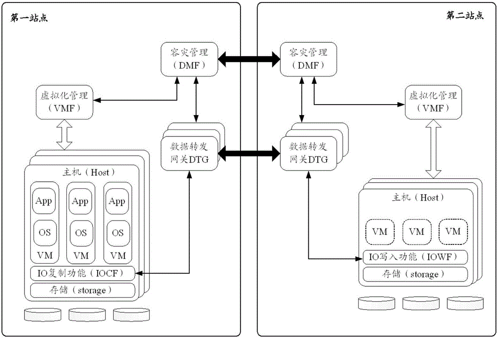
[0021] In order to facilitate the understanding of the embodiments of the present invention, first combine figure 1 Describe the architecture diagram of the applicable disaster recovery system of the embodiment of the present invention. The disaster recovery system includes a production site and a disaster recovery site. Each of the production site and the disaster recovery site has several hosts, virtualization management devices, and data transfer gateways (Data Transfer Gateway, DTG). The disaster recovery system also includes a disaster recovery management device, and the disaster recovery management device may be located at the production site or the disaster recovery site. There are several virtual machines (Virtual Machine, VM) running on the host, the IO copy function (IO Copy Function, IOCF) i...


PUM


Abstract

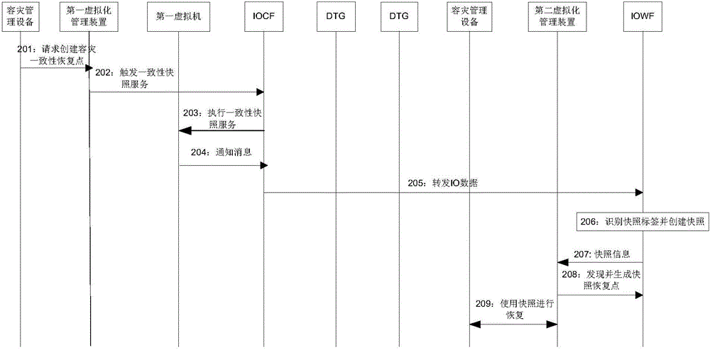
The embodiment of the invention provides a disaster tolerance method and disaster tolerance system, so that a consistency snapshot is created for a virtual machine of a production site at a disaster backup site. Specifically, a disaster tolerance management device determines a virtual machine whose consistency snapshot needs to be provided according to user demand or system configuration, determines an identifier of the virtual machine, sends a consistency snapshot request to a virtualization management device, the virtualization management device forwards the consistency snapshot request to IOCFs in a host where the virtual machine is, the IOCFs export IO data related with virtual machine consistency, and perform snapshot identification on the IO data. Based on the abovementioned disaster tolerance process, when the IO data are transmitted to IOWFs of the host where a disaster backup virtual machine of a disaster backup site is, and in the process of writing the IO data by the IOWFs, the snapshot identifier of the IO data is identified, and a disc snapshot is created at a finish point of the consistency snapshot corresponding to the snapshot identifier, thereby establishing consistency snapshots of all discs of the virtual machine at the disaster backup site.

Description

technical field [0001] The invention relates to the communication field, in particular to a disaster recovery method and a disaster recovery system. Background technique [0002] Disaster recovery technology refers to the establishment of two or more sets of systems with similar functions in distant places. When disasters such as earthquakes and fires occur at the production site, or major failures such as power outages occur, the business system of the production site cannot be normal. During operation, the ability to maintain continuous application services is maintained by switching the business system from the production site to a remote disaster recovery site. [0003] In a virtualized environment, create a disaster recovery virtual machine corresponding to the production site virtual machine at the disaster recovery site. The virtual machine IO operations on the production site will be intercepted, and the intercepted IO data will be transmitted to the disaster recove...

Claims


Application Information

Patent Timeline
Patent Type & Authority Applications(China)
IPC IPC(8): H04L12/24
Inventor 李珺
Owner HUAWEI TECH CO LTD
Why Eureka
Eureka Blog
Learn More