Method and test bench for testing an assembly of components of a vehicle

A combination, test bench technology, used in vehicle testing, mechanical component testing, machine/structural component testing, etc., that can address insufficient simulation and testing, delay time constraints, and insufficient simulation and testing of high dynamic control systems. process, etc.

Active Publication Date: 2019-05-17
AVL LIST GMBH
View PDF5 Cites 0 Cited by
  • Summary
  • Abstract
  • Description
  • Claims
  • Application Information

AI Technical Summary

Problems solved by technology

The dynamics of rotational acceleration are limited by the test rig cardan shaft (shaft between the loader and the axle or wheel) and by the actual power (torque, rotational speed) of the loader and by the delay times of the aforementioned system components of the test rig
Therefore highly dynamic braking processes can only be simulated and tested insufficiently with the aid of conventional test bench structures as described in DE 10 2006 035 502 B3
[0009] In summary, due to the limited dynamics of the test bench, highly dynamic test runs of the drive train or of the vehicle, in particular test runs involving interventions in the brake system, can only be carried out to a limited extent and therefore only insufficiently. simulated and tested

Method used


Image

  • Method and test bench for testing an assembly of components of a vehicle
  • Method and test bench for testing an assembly of components of a vehicle
  • Method and test bench for testing an assembly of components of a vehicle

Examples


Embodiment Construction

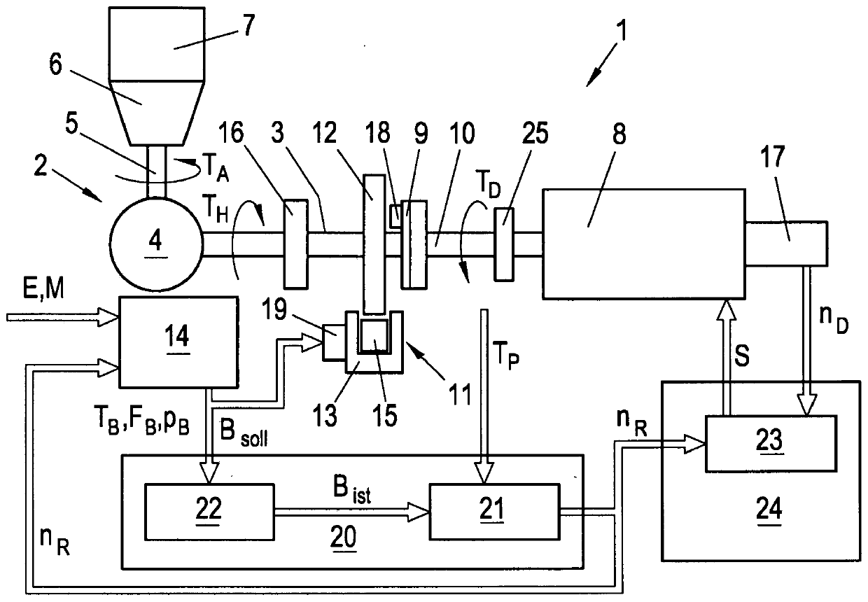
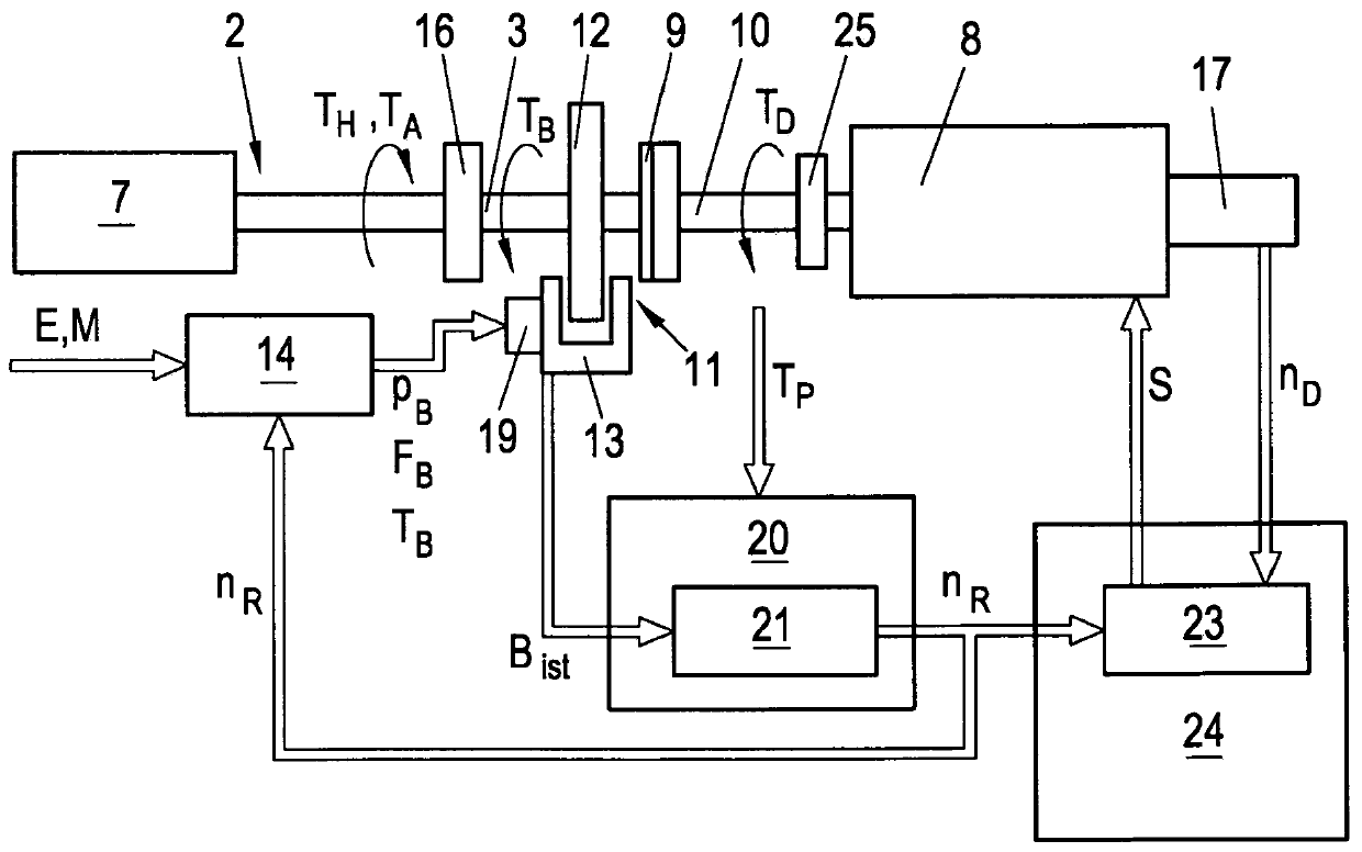
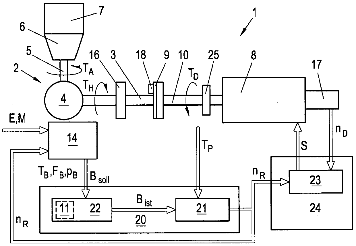
[0024] figure 1 A drive train test stand is shown schematically as test stand 1, which comprises a vehicle drive train 2, which here comprises sideshafts 3, a differential 4, a drive shaft 5 and a transmission 6 as real components, which are operatively Installed on test bench 1. The drive train 2 is driven by a drive 7, such as an internal combustion engine or an electric motor, and generates a drive torque T A , which induces a sideshaft moment T H . Hereinafter it is generally referred to as the drive train torque T P , which collectively refer to the torque acting in the drive train 2 . The drive train 2 is connected to a loader 8, preferably an electric loader (dynamometer). For this purpose, the loader 8 is connected in a rotationally fixed manner to the wheel 9 , possibly via a suitable load shaft 10 , such as a cardan shaft, only the wheel hub being shown here for the sake of simplicity. Loader 8 produces load torque T D , which is applied to the drive train 2 ...


PUM


Abstract

In order to be able to test the vehicle component assembly with better dynamics on the test stand, it is provided that in the simulation unit (20) by means of a simulation model (21) for at least one component of the assembly The drive train torque (T P ) and the braking effect (B) of the braking system (11) to calculate the instantaneous drive train speed of the component (n P ) and is used by the vehicle controller (14) using the calculated driveline speed (n P ) to control the at least one component, and the calculated drive train speed (n P ) to control the loader (8).

Description

technical field [0001] The invention relates to a method and a test stand for testing an assembly of components of a vehicle, the assembly comprising a drive train, at least one vehicle controller handling the rotational speed of the drive train and a brake acting on the drive train on the test stand A system wherein the driveline of the vehicle is driven by a drive unit and a load torque is applied to the driveline by means of a loader coupled to the driveline, and at least one component of the combination is controlled by a vehicle controller based on the speed of the driveline. Background technique [0002] There are many vehicle controllers in a vehicle, such as hybrid controller, engine controller, transmission controller, driving dynamics control system, etc., to name a few, which may be interconnected with each other via one or more vehicle buses. Many such vehicle controllers process speed either at the wheels such as via ABS speed sensors, or at drivetrain component...

Claims


Application Information

Patent Timeline
Patent Type & Authority Patents(China)
IPC IPC(8): G01M13/02G01M17/007
CPCG01M13/025G01M15/00G01M17/00G01M17/0072B60T8/00G01M13/027G01M17/007
Inventor F·普菲斯特
Owner AVL LIST GMBH
Why Eureka
Try Eureka