
A scara robot calibration method

A calibration method and robot technology, applied in instruments, measuring devices, optical devices, etc., can solve the problems of difficulty in guaranteeing zero-position calibration results, and achieve the effect of accurate absolute accuracy and easy zero-position calibration results.

Active Publication Date: 2019-01-04
天津新松机器人自动化有限公司
View PDF6 Cites 0 Cited by
  • Summary
  • Abstract
  • Description
  • Claims
  • Application Information

AI Technical Summary

Problems solved by technology

Although this method is simple to implement, it is difficult to guarantee the zero calibration result due to the influence of the assembly accuracy of the workpiece and the machining accuracy of the mechanical workpiece.

Method used


Image

  • A scara robot calibration method

Examples


Embodiment Construction

[0016] The specific embodiment of the present invention will be further described below in conjunction with accompanying drawing:

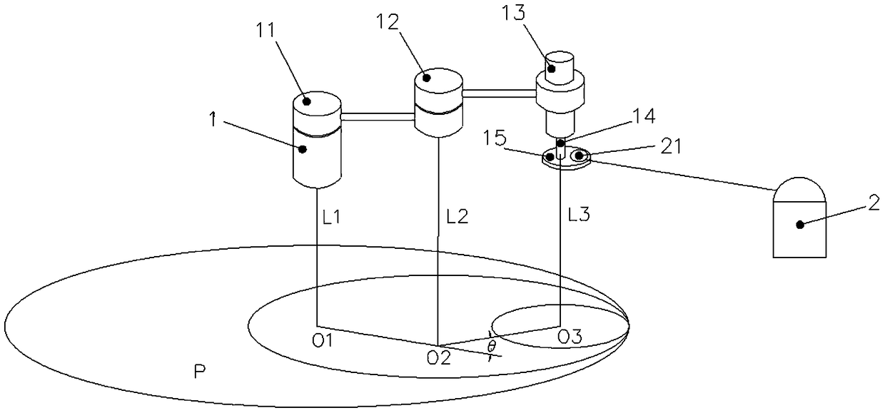
[0017] Such as figure 1 As shown, the SCARA robot 1 includes a first joint 11, a second joint 12, a third joint 13, a moving joint 14 and an end flange 15, the first joint 11 is connected to the second joint 12 through a connecting piece, and the second joint 12 The third joint 13 is connected by a connecting piece, the third joint 13 is axially installed with a movable joint 14 , and the end of the movable joint 14 is installed with an end flange 15 .

[0018] The calibration method of the SCARA robot is implemented by a laser reflection device 21 and a laser three-coordinate measuring device 2, and the laser three-coordinate measuring device 2 is a laser tracker or any other device with the same function.

[0019] Step 1, install the laser reflection device 21 on the flange 15 at the end of the SCARA robot to make the first joint 11 of the SCAR...


PUM


Abstract

The invention relates to the technical field of robot zero calibration, and particularly relates to an SCARA robot calibration method. The SCARA robot calibration method comprises the steps of installing a laser reflecting device on a tail end flange of an SCARA robot, enabling each single shaft of the SCARA robot to perform rotatory movements respectively, acquiring points on a circumference taking the rotation center as a circle center by using a laser three-coordinate measuring device at the same time, fitting the points into a circumference, and acquiring the position of the circle center and a rotation plane; making an axis, which passes the circle center of the corresponding shaft and perpendicular to the corresponding rotation plane, of each shaft, making a plane which passes the circle center of the first shaft and perpendicular to the axis of the first shaft, an intersection point of the axis of the other shafts and the plane is a new circle center, the intersection points of each two adjacent shafts on the plane are connected, an included angle of the adjacent connecting lines is a zero error, and compensation for the zero error is zero calibration. The three-coordinate measuring device is utilized, so that a zero calibration result is easy to be ensured compared with a method of only depending on coordination of a mechanical calibration workpiece, and the absolute precision of the robot is more accurate.

Description

technical field [0001] The invention relates to the technical field of robot zero calibration, in particular to a SCARA robot calibration method. Background technique [0002] The zero position is the datum of the robot coordinate system, without which the robot cannot judge its own position. Among the factors affecting the absolute accuracy of the robot, the zero position error accounts for as high as 97%. Robot zero error refers to the error value of the actual initial position of each axis of the robot relative to the theoretical position. Robot zero calibration is to accurately determine the zero value of the robot, thereby reducing the zero error and improving the absolute accuracy of the robot. The existing zero calibration method for industrial SCARA robots is to install calibration workpieces on the end flange of the robot and the robot base respectively, and realize zero calibration through the cooperation between the workpieces. Although this method is simple to...

Claims


Application Information

Patent Timeline
Patent Type & Authority Patents(China)
IPC IPC(8): G01B11/00
Inventor 张锋李学威徐方邹风山褚明杰花鹏
Owner 天津新松机器人自动化有限公司
Learn More