
An error identification method for zero position calibration of swing arm crawler robot

A crawler robot and identification method technology, applied in crawler vehicles, motor vehicles, transportation and packaging, etc., can solve the problems of return error, inability to know error, transmission error, etc., to achieve high-precision joint position measurement, high reliability, and realization of handy effect

Inactive Publication Date: 2017-04-05
NANJING UNI SPECIALIZED ROBOT TECH CO LTD
View PDF6 Cites 0 Cited by
  • Summary
  • Abstract
  • Description
  • Claims
  • Application Information

AI Technical Summary

Problems solved by technology

This method is an indirect way to obtain the absolute position of the joint, and two problems need to be solved: one is zero calibration, that is, since the incremental encoder measures the relative position of the shaft through pulses, zero calibration is required to obtain the absolute position of the joint ; the other is transmission error measurement, that is, because this method detects the position of the motor shaft, and then calculates the joint position required by the control target indirectly according to the theoretical transmission ratio, although the position of the motor shaft can be obtained by selecting a high-precision code. Position measurement accuracy, but it is impossible to know the error caused by the transmission mechanism from the motor to the end joint, resulting in the measured target position accuracy is not high, and the transmission mechanism error is mainly the return error, so how to obtain the return error is also a realization Key issues to be solved in high-precision position measurement
[0005] The most common solution at present is to install auxiliary position sensors such as absolute position encoders, rotary potentiometers, limit switches or infrared proximity switches on the joint axis to achieve zero calibration. On the one hand, this method requires the installation of additional sensors at the joint position , for crawler robots that require a compact structure, the flexibility of the mechanism design is greatly reduced, and the introduction of additional sensors at the movable joint position will reduce the reliability of the system; on the other hand, this method cannot solve the transmission problem caused by the reduction drive error identification problem

Method used


Image

  • An error identification method for zero position calibration of swing arm crawler robot
  • An error identification method for zero position calibration of swing arm crawler robot
  • An error identification method for zero position calibration of swing arm crawler robot

Examples


Embodiment 1

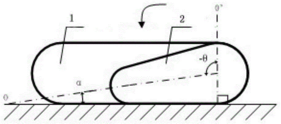
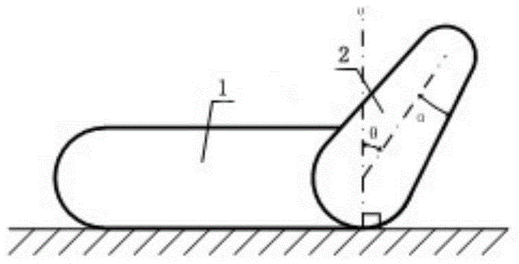
[0038] It is only assumed that the robot is a single-arm crawler structure, such as image 3 As shown, that is, the swing arm has only one movable joint. If there are multiple joints, the operation method is the same. It can be implemented at the same time without interfering with the active space, without waiting for completion one by one. The implementation steps of an accurate detection method are as follows: A. Place the robot flat on the site for preparation: place the robot on any flat space that can be supported flat, with a plane inclination ≤ 15°;

[0039] B. Friction torque detection: First, at a speed not greater than 1 / 2 of the motor rating, in speed mode, make the swing arm move continuously at an angle of about 10° within the range of the unsupported angle |θ|<90+α, and monitor the motor drive current at the same time. The average current in the state of uniform rotation is used as the drive current IF required to overcome the friction torque;

[0040] C. Positi...

Embodiment 2

[0044] Including: A. Place the robot in any plane space that can be supported horizontally, with a plane inclination ≤ 15°; B. Forward reference position detection: place the robot in any plane space that can be supported horizontally, and run in speed mode. First, make the swing arm rotate in the forward direction at 1 / 5 of the rated speed of the motor within the range of the unsupported angle |θ|<80+α, and at the same time monitor the filter drive of the motor drive current after a low-pass filter equivalent to the bandwidth of the speed loop The absolute value of the current ICF1, when the ICF1 appears more than 2 times the step mutation as the trigger source, record the encoder measurement value at this moment as the reference position value β1, and then control the reverse rotation of the swing arm to the starting point to stop;

[0045] C. Reverse reference position detection: After step B is completed, control the swing arm to rotate in the reverse direction at 1 / 5 of th...


PUM


Abstract

The invention discloses an error identification method for zero adjustment for a swing arm type tracked robot. The error identification method for the zero adjustment for the swing arm type tracked robot includes the zero adjustment which considers transmission mechanism return error and the zero adjustment which does not consider the transmission mechanism return error, if the robot is located in a large enough plane environment, a track body is located at a horizontal state under the situation that the robot is completely supported by the track body. According to the essence that the control for joint positions of the swing arm type tracked robot is aimed to adapt to the support and move needs of different road surfaces, the error identification method fully uses the common scene of which the plane is close to the horizontal plane, and the zero adjustment for swing arm joints can be realized through an incremental encoder arranged at a motor shaft without any other position detection sensor.

Description

technical field [0001] The invention relates to an error identification method for zero position calibration of a swing arm crawler robot. Background technique [0002] For the swing arm crawler robot, including the crawler body to realize the mobile drive, it consists of two or four rotatable swing arms. The position angle θ of the swing arm usually needs to be controlled in real time according to the terrain environment. The position control of the swing arm is a joint mechanism. As a special application of articulated mechanism, as the electric drive scheme usually adopted by articulated mechanism, the driving structure of typical articulated mechanism is to obtain the absolute position θ of the joint, which is the precondition for realizing precise position control. The joint transmission structure is through the motor through the coupling The drive drives the joint movement through a reduction drive. Due to factors such as cost, installation space, and precision requir...

Claims


Application Information

Patent Timeline
Patent Type & Authority Patents(China)
IPC IPC(8): B60W40/10B62D55/06
CPCB60W40/10B62D55/06
Inventor 王建谈英姿许映秋
Owner NANJING UNI SPECIALIZED ROBOT TECH CO LTD
Learn More