Unlock instant, AI-driven research and patent intelligence for your innovation.
Clothes hanger combined with bedside table
What is Al technical title?
Al technical title is built by PatSnap Al team. It summarizes the technical point description of the patent document.
A bedside table and hanger technology, applied in the field of hangers, can solve problems such as easy deformation, and achieve the effect of saving space and simple structure
Active Publication Date: 2022-05-20
NANJING POLYTECHNIC INSITUTE
View PDF11 Cites 0 Cited by
Summary
Abstract
Description
Claims
Application Information
AI Technical Summary
This helps you quickly interpret patents by identifying the three key elements:
Problems solved by technology
Method used
Benefits of technology
Problems solved by technology
[0002] At present, many households install clothes hooks on the bedroom door or kitchen cabinet door, which often brings inconvenience in terms of hanging and taking clothes in the morning and evening, especially in the cold winter, and the bedroom door or kitchen cabinet door is subjected to external forces for a long time. function, easy to deform, the combination of hangers and bedside tables not only saves space, but also makes hanging and taking clothes more convenient
Method used
Image
Click on the blue label to locate the original text in one second.
Reading with bidirectional positioning of images and text.
Examples
Embodiment Construction
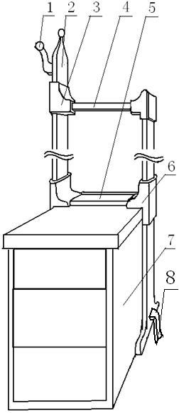
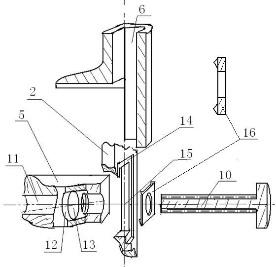
[0015] exist figure 1 Among them, the hook 1 is fixed on the outer side of the upper part of the longer column in the T-shaped column group 2. It is characterized in that: the upper part of the column of the T-shaped column group 2 is connected with the hanging rod 4, and the connection is covered with the upper connection cover 3. The T-shaped The middle and lower part of the column of the column group 2 is connected with the rectangular clamping plate 5, and the joint is covered with the lower connection cover 6, the rectangular clamping plate 5 is close to the cabinet surface of the bedside table 7, and the lower end of the column of the T-shaped column group 2 is connected to the 7 feet of the bedside table Consistent, the flat bottom band 8 traverses from the bottom of the bedside table 7, and is tightly tied to the lower end of the column of the T-shaped column group 2.
[0016] exist figure 2 Among them, the end of the hanging rod 4 is provided with a longitudinal adj...
PUM
Abstract
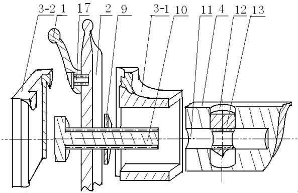
The hanger combined with the bedside table consists of a hook, a T-shaped column group, an upper connecting cover, a hanging rod, a rectangular clamping plate, a lower connecting cover, a bedside table, screws, hexagonal nut pieces, bolts, longitudinal adjustment holes, horizontal holes, and horizontal hole nuts , Anchor pad groove, card position adjustment hole, anchor pad, flat bottom belt, gear column groove, gear column, outer notch, inner notch, fix the hook on the upper outer side of the longer column in the T-shaped column group with screws , it is characterized in that: the upper part of the column of the T-shaped column group is connected with the hanging rod, and the connection is covered with an upper connection cover; the middle and lower part of the column of the T-shaped column group is connected with the rectangular clamping plate, and the connection is covered with a lower connection cover Wrapped, the rectangular clamp flat plate is close to the bedside table cabinet, the lower end of the column of the T-shaped column group is flush with the foot of the bedside table, and the flat bottom band traverses from the bottom of the bedside table, and is tightly tied to the lower end of the column of the T-shaped column group.
Description
technical field [0001] The invention relates to a clothes hanger, in particular to a clothes hanger combined with a bedside table. Background technique [0002] At present, many households install clothes hooks on the bedroom door or kitchen cabinet door, which often brings inconvenience in terms of hanging and taking clothes in the morning and evening, especially in the cold winter, and the bedroom door or kitchen cabinet door is subjected to external forces for a long time. Function, easy to deform, the combination of hanger and bedside table not only saves space, but also makes hanging and taking clothes more convenient. Contents of the invention [0003] The technical problem to be solved by the present invention is to provide a clothes hanger combined with the bedside table, adjust the position of the anchor pad so that the rectangular clamping flat plate is close to the table top of the bedside table, and then tighten the lower end of the T-shaped column and the flat...
Claims
Application Information
Patent Timeline
Application Date:The date an application was filed.
Publication Date:The date a patent or application was officially published.
First Publication Date:The earliest publication date of a patent with the same application number.
Issue Date:Publication date of the patent grant document.
PCT Entry Date:The Entry date of PCT National Phase.
Estimated Expiry Date:The statutory expiry date of a patent right according to the Patent Law, and it is the longest term of protection that the patent right can achieve without the termination of the patent right due to other reasons(Term extension factor has been taken into account ).
Invalid Date:Actual expiry date is based on effective date or publication date of legal transaction data of invalid patent.



