Supercharge Your Innovation With Domain-Expert AI Agents!

Stirring device and method for preventing storage bin of discharging machine of stirrer from being fully blocked

A stirring device and storage bin technology, applied to mixers with rotating stirring devices, mixer accessories, chemical instruments and methods, etc., can solve problems such as inability to stir and discharge materials, low efficiency, and stalled rotors, and achieve Avoid clogging, fully stir and reduce damage

Inactive Publication Date: 2017-05-10
JIASHAN YONGJIN METAL PROD
View PDF2 Cites 0 Cited by
  • Summary
  • Abstract
  • Description
  • Claims
  • Application Information

AI Technical Summary

Problems solved by technology

[0002] Mixer is an indispensable equipment in the field of mechanical processing and production. It can mix different raw materials together, and can also mix and match ready-made materials into a new material. The commonly used mixer is equipped with a feeding pipe at the top and a stirring at the bottom. During the use of the mixer, the amount of material in the storage warehouse of the mixer feeding machine cannot be controlled so that the storage material is too full. The stirring motor of the mixing chamber is often blocked and burns out the motor. At the same time, it cannot achieve the effect of stirring and discharging. It is not high; and there is only one stirring shaft in the commonly used mixer, and the stirring efficiency is not high, so it is necessary to design a device that can be controlled in order to achieve normal and safe use and high stirring efficiency

Method used


Image

  • Stirring device and method for preventing storage bin of discharging machine of stirrer from being fully blocked
  • Stirring device and method for preventing storage bin of discharging machine of stirrer from being fully blocked
  • Stirring device and method for preventing storage bin of discharging machine of stirrer from being fully blocked

Examples


Embodiment Construction

[0020] In order to make the technical means, creative features, goals and effects achieved by the present invention easy to understand, the present invention will be further elaborated below in conjunction with illustrations and specific embodiments.

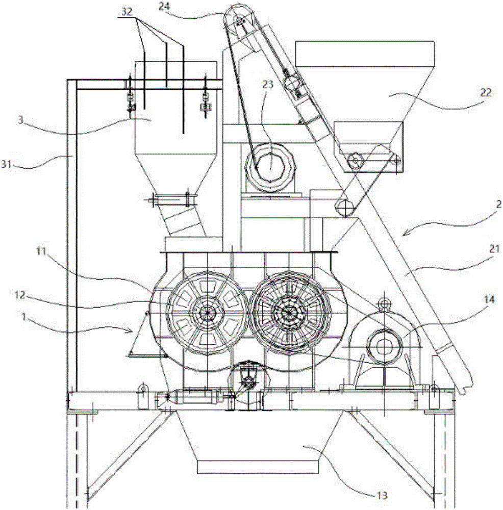
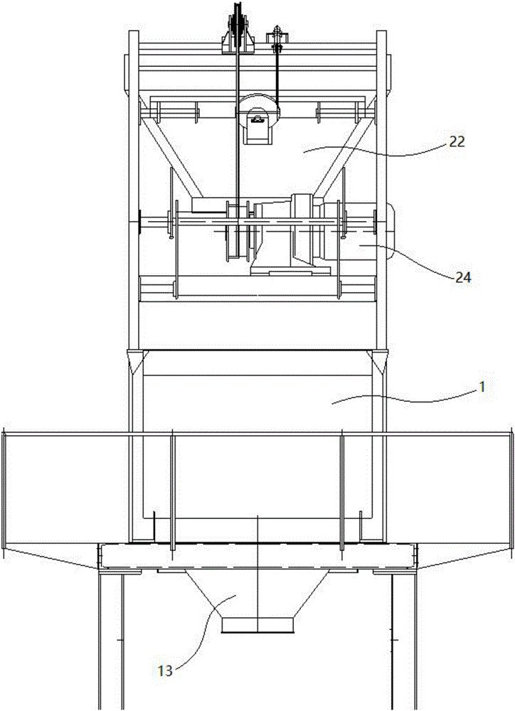
[0021] refer to figure 1 , figure 2 , image 3 , Figure 4 As shown, this agitating device includes a feeder 1, a material lifting mechanism 2 and a feed tank 3, the feed tank 3 is located at the upper end of the feeder 1, and the material lifter 2 is located at the feed tank 3 One side of the blanking machine 1 is provided with a storage bin 11, a stirring shaft 12 and a discharge tank 13, one side of the blanking machine 1 is provided with a stirring drive mechanism 14, and the stirring shaft 12 is provided with a Right and located in the storage bin 11, the stirring drive mechanism 14 is connected with the stirring shaft 12 by a transmission belt, and the upper end of the storage bin 11 is connected with the bottom end of...


PUM


Abstract

A stirring device comprises a discharging machine, a material lifting mechanism and a feeding tank, wherein the feeding tank is located at the upper end of the discharging machine; the storage bin, a pair of stirring shafts and a discharging tank are arranged in the discharging machine; a stirring drive mechanism is connected with the stirring shafts through a transmission belt; the upper end of the storage bin is connected with the bottom end of the feeding tank through a feeding pipe; the storage bin and the stirring drive mechanism are both mounted on a support at the lower end of the discharging machine; the discharging tank is arranged at the bottom end of the storage bin; the stirring shafts are arranged in the material storage bin, stirring is more sufficient and the stirring efficiency is higher in the stirring process; an electricity conduction device is arranged at the top end of the feeding tank. Different circuits are connected through switching of material levels at different heights in the feeding tank, different signals are produced and sent to a PLC (programmable logic controller), a material lifting drive mechanism is controlled to be started and shut off by the PLC, materials in the feeding tank are controlled, the discharging machine is prevented from being fully blocked, and damage to a drive motor is reduced.

Description

technical field [0001] The invention relates to the field of mechanical processing and production, in particular to a stirring device and a method for avoiding the blockage of the storage bin of the mixer feeder. Background technique [0002] Mixer is an indispensable equipment in the field of mechanical processing and production. It can mix different raw materials together, and can also mix and match ready-made materials into a new material. The commonly used mixer is equipped with a feeding pipe at the top and a stirring at the bottom. During the use of the mixer, the amount of material in the storage warehouse of the mixer feeding machine cannot be controlled so that the storage material is too full. The stirring motor of the mixing chamber is often blocked and burns out the motor. At the same time, it cannot achieve the effect of stirring and discharging. It is not high; and only one stirring shaft is arranged in the commonly used mixer, and the stirring efficiency is no...

Claims


Application Information

Patent Timeline
Patent Type & Authority Applications(China)
IPC IPC(8): B01F7/04B01F15/02B01F15/00
CPCB01F27/2322B01F27/706B01F35/22B01F35/2212B01F35/717
Inventor 张玲玲
Owner JIASHAN YONGJIN METAL PROD
Features
  • R&D
  • Intellectual Property
  • Life Sciences
  • Materials
  • Tech Scout
  • Unparalleled Data Quality
  • Higher Quality Content
  • 60% Fewer Hallucinations
Learn More