
Scrap cutter for blanking die

A technology for scrap cutters and molds, which is applied in the directions of rolling out equipment, transportation and packaging, vehicle parts, etc., and can solve problems such as damage and affecting the surface quality of covering parts.

Active Publication Date: 2018-06-19
东莞市骏毅机电科技有限公司
View PDF9 Cites 0 Cited by
  • Summary
  • Abstract
  • Description
  • Claims
  • Application Information

AI Technical Summary

Problems solved by technology

There is a compression spring on the ejector rod of the die core. When the die core punches the product, the product will drop together with the die. After the punching is completed, the die core rises, and the die ejector rod drives the die under the restoring force of the compression spring. Rising, because the die will swing during the rising process, causing the edge of the cover to rub against the inner cavity of the die, causing damage and affecting the surface quality of the cover

Method used


Image

  • Scrap cutter for blanking die
  • Scrap cutter for blanking die

Examples


Embodiment Construction

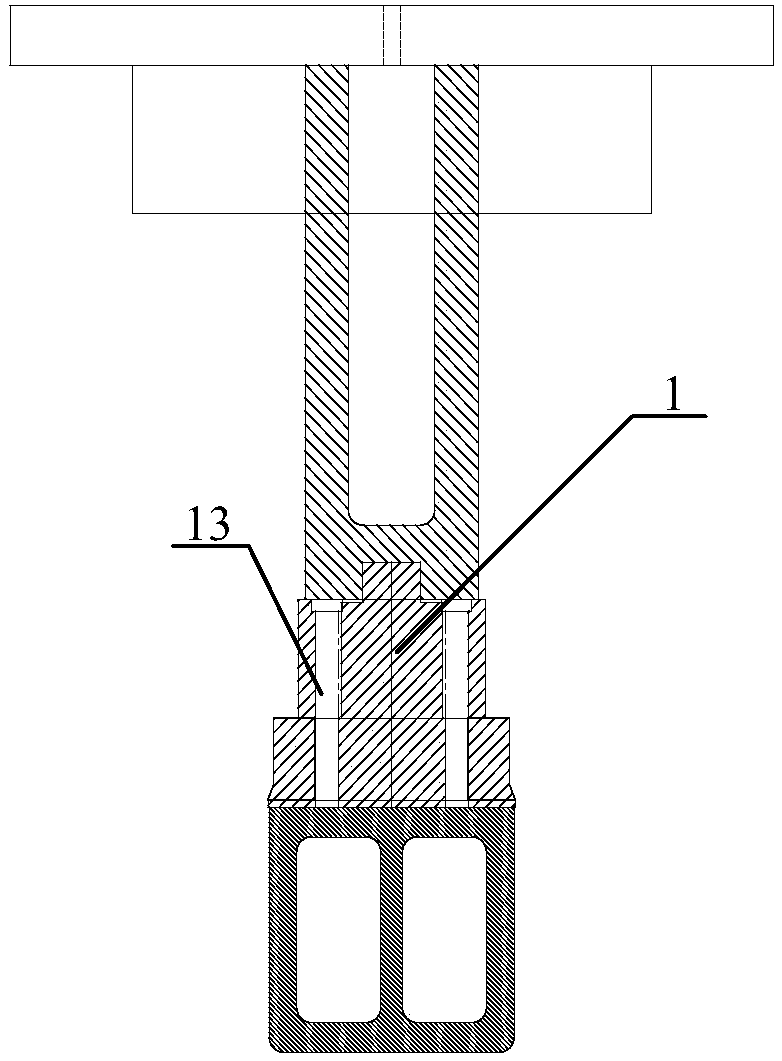
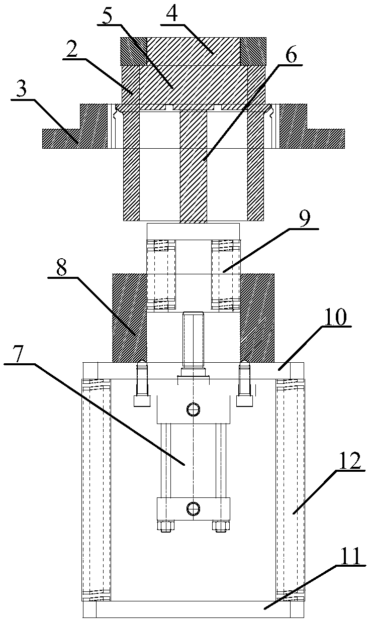
[0026] The invention discloses a waste material cutter of a blanking die, which can reduce the damage to the edge of a cover part during the waste material cutting process by the waste material cutter.

[0027] The following will clearly and completely describe the technical solutions in the embodiments of the present invention with reference to the accompanying drawings in the embodiments of the present invention. Obviously, the described embodiments are only some, not all, embodiments of the present invention. Based on the embodiments of the present invention, all other embodiments obtained by those of ordinary skill in the art without creative efforts shall fall within the protection scope of the present invention.

[0028] see figure 1 and figure 2 , figure 1 A schematic structural view of the punch of the scrap cutter of the blanking die provided by the embodiment of the present invention; figure 2 It is a schematic diagram of the structure of the scrap cutter of the...


PUM


Abstract

The invention discloses a waste cutter for a blanking mould. The waste cutter for the blanking mould comprises a convex mould, a concave mould, a movable seat, a lower mould seat, a concave mould ejector rob, an air cylinder, a fixing sleeve and a first spring mounting plate. Owing to the fact that a product is driven to descend a certain distance by the concave mould ejector rob when blanking is conducted, the concave mould ejector rob only needs to descend a short distance when blanking is conducted, and the sum of the first-time descending height and the second-time descending height of the concave mould ejector rob is the blanking height. When blanking is conducted by the waste cutter for the blanking mould, the product only needs to descend the second-time blanking height. After blanking is finished, the rebound distance of the concave mould ejector rob under the restoring force effect of first compression springs is also the distance of the second-time seconding height. Compared with the prior art, the rebound distance of the concave mould ejector rob under the restoring force effect of the first compression springs is shortened, restoring force provided by the first compression springs is relatively reduced, and thus damage caused to the edges of covering parts is lowered.

Description

technical field [0001] The invention relates to the technical field of metal processing, in particular to a scrap cutter for a blanking die. Background technique [0002] Die design and manufacturing technology is the core technology of modern stamping production. With the rapid development of modern manufacturing industry, while the related automobile industry is pursuing high-efficiency, safe and reliable production, the requirements for the quality of spare parts are also increasing, especially the quality of core parts. The quality, especially the appearance requirements are getting higher and higher. [0003] Covering parts in the automotive industry have the characteristics of thin materials, complex shapes, large structural dimensions, and high surface quality requirements. The waste of the covering part has a large size and a complicated trimming shape. It is impossible to use the general unloading ring to unload the material. It needs to be cut off by the waste cut...

Claims


Application Information

Patent Timeline
Patent Type & Authority Patents(China)
IPC IPC(8): B21D28/14B21D45/04B21D53/88
CPCB21D28/14B21D45/04B21D53/88
Inventor 陈鸿宣康天明邓银桥
Owner 东莞市骏毅机电科技有限公司
Learn More