Laser cutting machine air filter unit

An air filter device, laser cutting machine technology, applied in combination device, laser welding equipment, dispersed particle separation, etc., can solve problems such as inability to effectively discharge smoke and dust, inability to reduce environmental pollution, etc.

Active Publication Date: 2017-05-10
南通国密祺机械设备有限公司
View PDF9 Cites 0 Cited by
  • Summary
  • Abstract
  • Description
  • Claims
  • Application Information

AI Technical Summary

Problems solved by technology

[0006] In order to overcome the shortcomings of being unable to effectively discharge smoke and reduce environmental pollution, the technical problem to be solved by the present invention is to provide an air filter device for laser cutting machines that can effectively discharge smoke and reduce environmental pollution

Method used


Image

  • Laser cutting machine air filter unit
  • Laser cutting machine air filter unit
  • Laser cutting machine air filter unit

Examples


Embodiment 1

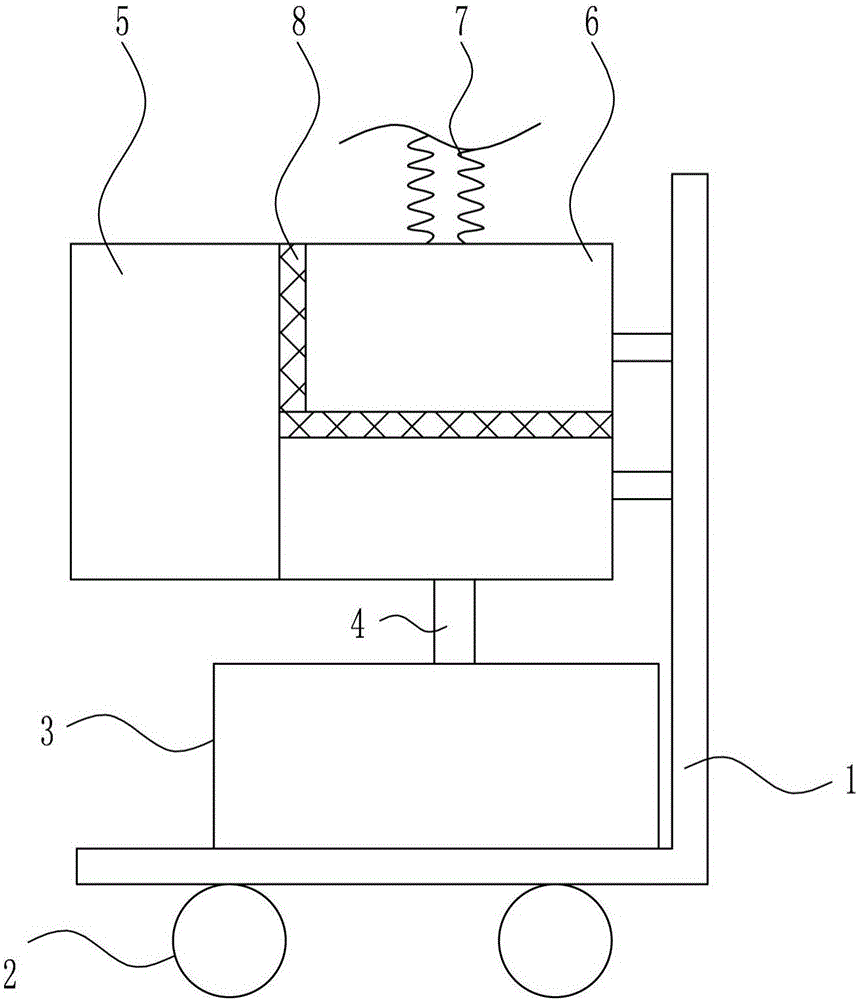
[0029] A laser cutting machine air filter device, such as Figure 1-4 As shown, it includes an L-shaped base 1, a universal wheel 2, a purification mechanism 3, a liquid outlet pipe 4, a spraying device 5, a storage box 6, a suction pipe 7 and a first filter screen 8, and the bottom of the L-shaped base 1 is connected symmetrically There are universal wheels 2, the top of the L-shaped base 1 is connected with a purification mechanism 3, the upper right side of the L-shaped base 1 is connected with a storage box 6, the top of the storage box 6 is connected with a suction pipe 7, and the middle part of the storage box 6 is connected to the storage box. 6, the upper left side is connected with the first filter screen 8, the left side of the placement box 6 is connected with the sprinkler 5, and the liquid outlet pipe 4 is connected between the bottom of the placement box 6 and the purification mechanism 3.

Embodiment 2

[0031] A laser cutting machine air filter device, such as Figure 1-4 As shown, it includes an L-shaped base 1, a universal wheel 2, a purification mechanism 3, a liquid outlet pipe 4, a spraying device 5, a storage box 6, a suction pipe 7 and a first filter screen 8, and the bottom of the L-shaped base 1 is connected symmetrically There are universal wheels 2, the top of the L-shaped base 1 is connected with a purification mechanism 3, the upper right side of the L-shaped base 1 is connected with a storage box 6, the top of the storage box 6 is connected with a suction pipe 7, and the middle part of the storage box 6 is connected to the storage box. 6, the upper left side is connected with the first filter screen 8, the left side of the placement box 6 is connected with the sprinkler 5, and the liquid outlet pipe 4 is connected between the bottom of the placement box 6 and the purification mechanism 3.

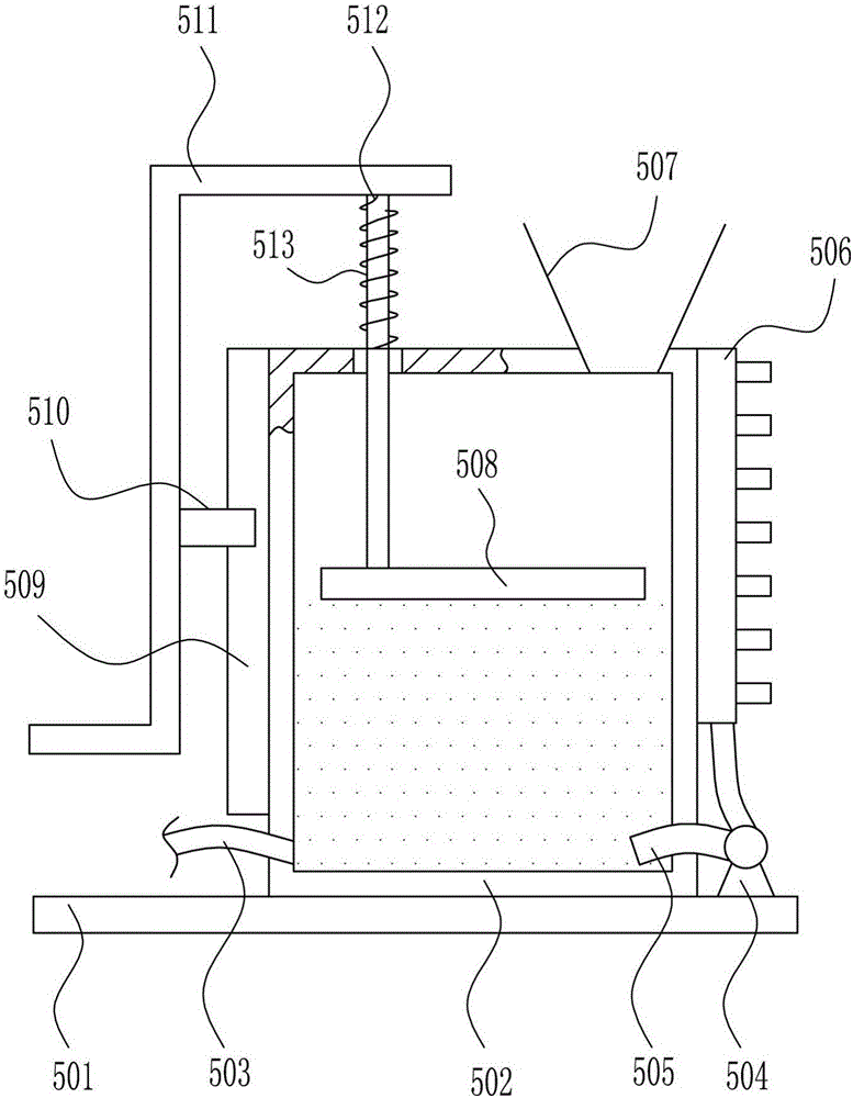
[0032] The sprinkler 5 includes a fixed plate 501, a first water tank 502,...

Embodiment 3

[0034] A laser cutting machine air filter device, such as Figure 1-4 As shown, it includes an L-shaped base 1, a universal wheel 2, a purification mechanism 3, a liquid outlet pipe 4, a spraying device 5, a storage box 6, a suction pipe 7 and a first filter screen 8, and the bottom of the L-shaped base 1 is connected symmetrically There are universal wheels 2, the top of the L-shaped base 1 is connected with a purification mechanism 3, the upper right side of the L-shaped base 1 is connected with a storage box 6, the top of the storage box 6 is connected with a suction pipe 7, and the middle part of the storage box 6 is connected to the storage box. 6, the upper left side is connected with the first filter screen 8, the left side of the placement box 6 is connected with the sprinkler 5, and the liquid outlet pipe 4 is connected between the bottom of the placement box 6 and the purification mechanism 3.

[0035] The sprinkler 5 includes a fixed plate 501, a first water tank 50...


PUM


Abstract

The invention relates to the field of laser cutting machines, in particular to a laser cutting machine air filter unit. The invention aims at achieving the technical purpose of providing the laser cutting machine air filter unit capable of discharging smoke dust and reducing environmental pollution effectively. To achieve the technical purpose, the invention provides the laser cutting machine air filter unit. The laser cutting machine air filter unit comprises an L-shaped base, universal wheels, a purifying mechanism, an outlet pipe, a spraying device, a putting case and the like; the bottom of the L-shaped base is connected to the universal wheels symmetrically, the top of the L-shaped base is connected to the purifying mechanism, the upper portion of the right side inside the L-shaped base is connected to the putting case, the top of the putting case is connected to an aspiration channel, and the middle part and the upper portion of the left side inside the putting case are both connected to a first strainer. According to the laser cutting machine air filter unit, the aspiration channel and an air outlet of the laser cutting machine are firstly connected, and when the laser cutting machine works, the massive smoke dust generated on an operation table of the laser cutting machine is sucked into the putting case.

Description

technical field [0001] The invention relates to the field of laser cutting machines, in particular to an air filter device for a laser cutting machine. Background technique [0002] Laser cutting machine is the energy released when the laser beam is irradiated on the surface of the workpiece to melt and evaporate the workpiece, so as to achieve the purpose of cutting and engraving. Smooth, low processing cost and other characteristics. [0003] When the commonly used laser cutting machine is in operation, the operating table will generate a lot of smoke and dust. If the smoke and dust are not discharged in time, if they accumulate in the operation workshop, it will easily pollute the working environment and damage the health of the operators. Conducive to the air circulation in the workshop. [0004] Therefore urgently need to research and develop a kind of laser cutting machine air filtering device that can effectively discharge smoke and dust, reduce environmental pollut...

Claims


Application Information

Patent Timeline
IPC IPC(8): B23K26/38B23K26/16B23K26/70B01D50/00
CPCB23K26/16B23K26/38B23K26/702B01D50/60
Inventor 费浩亮
Owner 南通国密祺机械设备有限公司
Why Eureka
Try Eureka